 listicle
Five Best Practices for Precision Gear Milling
Last Updated: November 6, 2026
Quick Summary
Precision gear milling starts with a geared milling cutter matched to your module, pressure angle, and tooth count, then follows disciplined cutting parameters, a true setup, consistent toolpath direction, and inspection that catches drift early. Set surface speed from the material first, convert it to spindle RPM using the cutter diameter, and set feed per tooth rather than feed per revolution.
- Match the cutter's form to your gear geometry, since a near-match measures wrong.
- Convert surface speed to spindle RPM with RPM = (SFM × 3.82) ÷ cutter diameter in inches.
- Take a cleanup pass and measure tooth thickness before cutting full gear groove depth.
- Climb mill the finishing pass and keep index angles consistent across every tooth.
- Measure tooth thickness, spacing, and profile after the first few teeth, not the last.
Table of Contents
- Start With the Right Gear Milling Tools
- Dial In Gear Milling Cutting Parameters Before the First Cut
- Get Gear Blank Setup and Fixturing Right
- Hold the Tooth Profile With Toolpath Direction and Indexing
- Use Gear Tooth Inspection Methods That Catch Drift Early
- Match the Method to the Job: Milling, Five-Axis, and High-Speed Machining
- Send Your Gear Project to VanderLab
- Frequently Asked Questions
Start With the Right Gear Milling Tools
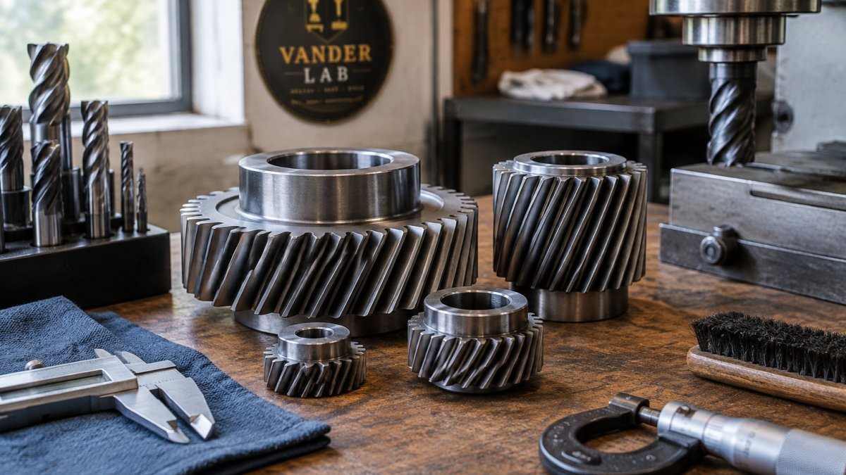
Precision gear milling starts with the cutting tool, not the machine.
The same rule holds across most machining work: the cutter decides what the workpiece can become. Pick wrong and no amount of careful setup saves the tooth profile.
Here's what actually drives cutter selection for gear teeth:
- Module and pressure angle match. The cutter's form must match the gear geometry you're cutting. A near-match produces a tooth that looks right and measures wrong.
- Tooth count range. Form-relieved cutters are sized for a range of teeth. Stay inside that range or the involute curve drifts.
- Coating and substrate. Hardened gear blanks chew through uncoated high-speed steel. Coated carbide holds up longer in high-speed machining.
- Radial vs. side clearance. Deep gear groove depth needs clearance behind the cutting edge, or the cutter rubs instead of cuts.
A common mistake is buying one general-purpose end mill and expecting it to cut gear forms. Gear milling needs a cutter ground to the profile, and the ANSI/AGMA gear classification standards exist precisely because tooth accuracy is measured, not eyeballed.
The second mistake is overspending on precision. A gear machining process guide notes that chasing greater accuracy raises cost, so match tolerance to the application. A decorative gear doesn't need the same cutter as a drive gear.
Dial In Gear Milling Cutting Parameters Before the First Cut
Cutting parameters decide whether your gear milling leaves a clean surface finish or a burned tooth.
There's no universal chart, and anyone who hands you one is guessing about your machine.
A practical approach, one project at a time:
- Set surface speed from the material first. Surface speed (surface feet per minute, or SFM) is the variable you anchor to. Softer, gummier metals tolerate higher surface speed; hardened blanks need lower surface speed and more coolant. Change surface speed before you touch anything else.
- Convert surface speed to spindle RPM using the cutter diameter. RPM = (SFM × 3.82) ÷ cutter diameter in inches. A larger form cutter spins slower for the same surface speed, that's why the same SFM number gives very different RPM on a small end mill versus a geared milling cutter.
- Set feed per tooth, not feed per revolution. Chip load per tooth controls tool wear and surface finish far better than table feed alone. Feed per tooth × number of teeth × RPM gives you the feed rate. Too light a chip load rubs and work-hardens; too heavy a chip load deflects the cutter and throws off tooth spacing.
- Start with a light depth of cut and a cleanup pass. Take a cleanup pass, measure tooth thickness and spacing, then take the full gear groove depth. On deep gear forms, a full-depth first pass is where deflection starts.
- Watch chip color and sound, not just the number. Blue or purple chips mean heat is building, back off surface speed or add coolant. Chatter means the setup is flexing, not that the parameters are wrong; fix rigidity before you chase the feed rate.
- Record what worked, per material and per cutter. Repeatability comes from notes, not memory. A small-batch shop that logs its winning parameters for each material and cutter combination stops re-learning the same lesson.
Material-specific adaptation is where most parameter advice falls apart.
For a deeper walkthrough of holding accuracy through the whole cut, our guide on how to ensure tight tolerances in machining covers the full process.
Watch out: running a full-depth gear cut on the first pass on a flexible setup can deflect the cutter and throw off gear tooth spacing before you ever measure it.
Get Gear Blank Setup and Fixturing Right
Workholding is where precision gear milling quietly succeeds or fails. A gear blank that shifts even slightly during the cut ruins indexing, and no inspection method catches a problem that started at the fixture.
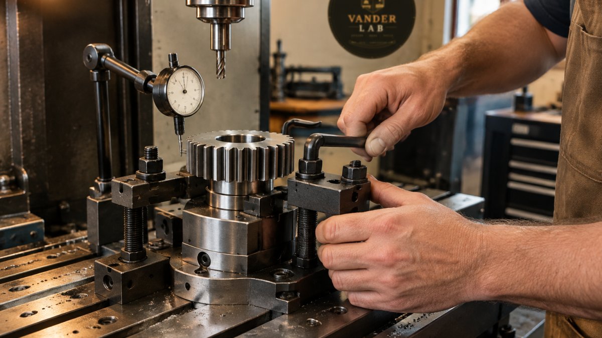
The setup checklist we run through:
- Clean the table and fixture faces. A chip under the blank is a tolerance error you can't see.
- Seat the blank on a true datum. Locate from the bore or a machined face, not a rough edge.
- Clamp evenly. Uneven clamping distorts thin blanks and springs them back after the cut.
- Indicate the blank before cutting. Confirm runout with a dial indicator, then re-check after the first pass.
- Calibrate the machine on a schedule. A machine that drifts between jobs produces gears that drift with it.
If you're designing parts and want tolerances that stay achievable from the start, our guide on how to design parts for tighter tolerances walks through the design decisions that make fixturing simpler.
Hold the Tooth Profile With Toolpath Direction and Indexing
Toolpath direction and indexing control the tooth profile after the cutter and setup are settled. Climb milling on the finishing pass, consistent index angles, and a verified starting position keep gear geometry true across every tooth.
Two things go wrong here more than anywhere else. First, mixing conventional and climb milling on the same gear leaves mismatched surface finish on alternating flanks. Second, indexing errors compound: a small error at tooth one becomes a large error at tooth twenty.
Toolpath consistency matters as much as cycle time. A steady, predictable path with slightly longer cycle time beats a fast path that leaves one flank different from the next.
For gear tooth spacing, verify your indexing angle against the number of teeth before the first cut, and re-check after every few teeth. On small-batch production and single-part production, that habit costs minutes and saves the part.
Use Gear Tooth Inspection Methods That Catch Drift Early
Inspection during the cut catches drift before it becomes scrap. Most gear-milling guides promise accuracy and then never explain how to verify it.
Measure tooth thickness, spacing, and profile after the first few teeth, not after the last one. The practical inspection set for gear milling:
- Tooth thickness with a gear tooth caliper or a span measurement over a fixed number of teeth. Span measurement is the more repeatable of the two because it references multiple flanks at once; a caliper is faster for a quick check. Compare against the theoretical chordal thickness for your module and pressure angle.
- Tooth spacing by indexing check across several teeth. Pick a reference tooth, zero an indicator on a flank, index to the next tooth, and read the deviation. Do this across a spread of teeth, first, middle, and last, not just adjacent ones, because indexing error compounds.
- Profile and lead with a dedicated gear inspection instrument on higher-precision parts. For shop-floor work, an involute check on a gear measuring center confirms the flank shape; for looser parts, a profile projector or optical comparator against an overlay is enough to catch gross form error.
- Runout with a dial indicator on the gear blank and on the finished tooth tips. Runout that appears after the cut points back to fixturing or clamping, not the cutter.
- Surface finish visually and by touch on the working flanks, and with a surface roughness tester when the spec calls for a number. A finish that changes from tooth to tooth is a toolpath or indexing signal, not a cutter signal.
Drift usually shows up as a trend, not a single bad tooth. If tooth three is slightly off and tooth ten is further off, stop and check the setup, not the cutter.
A practical habit: record the first-tooth reading, the mid-run reading, and the last-tooth reading on every small-batch job.
Match the Method to the Job: Milling, Five-Axis, and High-Speed Machining
Gear milling isn't always the right answer, and knowing when to switch methods protects both part quality and manufacturing efficiency. Match the cutting method to the gear geometry, quantity, and precision required.
| Method | Best For | Tradeoff |
|---|---|---|
| Gear milling | Small-batch production, single-part production, complex geometries | Slower cycle time than dedicated gear cutting |
| Five-axis machining | Complex gear parts, angled features, fewer setups | Higher machine cost and programming skill |
| High-speed machining | Finishing passes, better surface finish, reduced tool wear | Needs rigid setups and careful parameter control |
| Gear shaping | Internal gears, high-volume production | Dedicated tooling, less flexible for one-offs |
A gear-milling comparison from a technical gear milling vs. hobbing analysis makes the same point: milling wins on flexibility and adaptability, while dedicated methods win on volume.
The contrarian take: don't default to five-axis because it sounds more advanced. For a simple spur gear in small quantities, a well-set-up three-axis milling machine with the right cutter and indexing will match the result for less setup time.
Send Your Gear Project to VanderLab
Precision gear milling rewards preparation: the right cutter, disciplined parameters, a true setup, consistent toolpath, and inspection that catches drift early. Get those five right and the gear geometry takes care of itself.
If you'd rather hand the job to someone who works this way, we can help. You can order custom machined parts through a simple step-by-step process, request Custom Quotes for a project of your own, or browse our Ebay Shop for ready-made pieces, and check our guide to the cost of custom CNC machining before you commit. If you're still shaping the design, how to design machine-ready parts will save you a round of revisions.
Reach out to VanderLab to talk through your gear part.
Frequently Asked Questions
What is precision gear milling?
Precision gear milling cuts gear teeth with a rotating milling cutter on a CNC machining center, removing material tooth by tooth instead of generating the whole profile at once. It suits small-batch production, single-part production, and complex geometries where a custom setup beats dedicated hobbing equipment. Because each tooth is indexed and cut individually, the result depends on rigid workholding, correct cutter selection, and steady cutting parameters. Get those right and gear milling holds tight tolerances on gear parts from prototypes to short production runs.
How do you improve accuracy when milling gears?
Accuracy comes from controlling the variables around the cut, not from chasing the highest possible precision spec. Start with a rigid gear blank setup and fixturing, verify alignment with a dial indicator, and keep tool engagement consistent through the pass. Use cutting parameters that avoid chatter, and confirm tooth spacing with an indexing check before finishing. A gear-machining guide notes that pushing precision higher than the application needs adds cost, so match dimensional accuracy to what the gear actually does.
How do you choose cutting parameters for gear milling?
Set gear milling cutting parameters around the material, the cutter, and the rigidity of the setup. Start conservative on speed and feed, watch chip formation and surface finish, then increase until chatter or tool wear appears. Keep tool engagement steady and avoid dwelling in the gear groove depth. Because every machine and fixture behaves differently, treat published parameters as a starting point and tune from there. Record what works so the next run repeats it instead of starting over.
How should a gear blank be fixtured for milling?
Fixture the gear blank so it cannot move or deflect during the cut. Clamp close to the cutting zone, support the underside, and check runout with a dial indicator before cutting. For round blanks, a chuck or collet on a rotary axis keeps the centerline true; for odd shapes, a custom fixture plate machined to match pays for itself in repeatability. Confirm gear blank setup and fixturing on scrap or a first article, then lock the process in for the rest of the batch.
When should a gear be milled instead of hobbed?
Gear milling fits small-batch production, single-part production, and jobs with complex geometries or unusual tooth profiles where hobbing tooling would cost more than it saves. Hobbing wins on high-volume runs of standard gears because it generates teeth faster. A technical and economic comparison of the two methods shows the decision usually comes down to quantity and tooling cost. For a prototype or a handful of replacement gears, milling on a CNC machining center is often the faster, more flexible path.