 ultimate-guide
How to Ensure Tight Tolerances in Machining: 2026 Guide
Table of Contents
- What Tight Tolerances Actually Mean on the Shop Floor
- Common Causes of Machining Errors and How to Catch Them Early
- The Importance of Workholding in CNC Accuracy
- How to Measure Machining Tolerances Without Guesswork
- CNC Machine Calibration Best Practices for Repeatable Results
- Design Decisions That Make Tight Tolerances Achievable
- Frequently Asked Questions
Last Updated: September 24, 2026
What Tight Tolerances Actually Mean on the Shop Floor
Tight tolerances in machining describe a part specification where the allowable deviation from the nominal dimension is very small, often measured in thousandths of an inch or finer. A tolerance of ±0.001 in. leaves no room for guesswork; every variable in the process has to be understood and controlled. Tight tolerances are a system, not a single setting.
The practical definition matters more than the number. A tight tolerance is any tolerance that approaches the limit of your machine, your tooling, and your measurement equipment combined.
Common Causes of Machining Errors and How to Catch Them Early
Most machining errors trace back to a short list: thermal growth, vibration, workholding deflection, tool wear, and measurement error. Catching them early means instrumenting the process, not just inspecting the part at the end.
- Tool wear: a dull cutter pushes harder, deflects more, and drifts out of tolerance
- Chip recutting: poor evacuation raises temperature and degrades surface finish
- Fixture slip: a part that moves mid-cut ruins the whole feature
- Setup error: a wrong offset or datum shift throws every dimension off consistently
Thermal Expansion and Vibration: The Two Hidden Error Sources
Thermal expansion is the change in a part's dimensions as its temperature changes. The math is simple enough to run on a shop floor: dimensional change equals the part's length, times the material's coefficient of thermal expansion, times the temperature change. Aluminum's coefficient is roughly 13 micro-inches per inch per degree Fahrenheit, so a 10 in. aluminum part grows about 0.00013 in. for every 1°F rise.
The practical compensation workflow has four steps:
- Establish a reference temperature. Most shops use 68°F as the standard reference, matching the temperature at which gage blocks and many inspection standards are specified.
- Measure the actual part temperature at inspection, not the ambient air. A non-contact infrared thermometer or a surface probe on the part itself gives a truer reading than a wall thermometer.
- Calculate the correction. Multiply length × coefficient × (part temp − 68°F) to get the expected growth, then subtract it from the measured value before comparing to the print.
- Log the correction alongside the inspection result so the pattern is visible over a run.
The Importance of Workholding in CNC Accuracy
Workholding determines how much a part moves under cutting force. A part held rigidly cuts accurately; a part held loosely deflects, chatters, and drifts. The importance of workholding in CNC work cannot be overstated, because no amount of machine precision compensates for a workpiece that shifts.
- Minimize tool overhang to reduce deflection
- Use fixtures that repeat the same datum every cycle
- Torque clamps consistently so setup is repeatable
- Deburr and clean locating surfaces before every load
How to Measure Machining Tolerances Without Guesswork
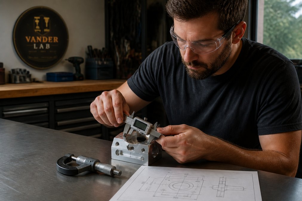
How to measure machining tolerances comes down to matching the instrument to the tolerance. The ten-to-one rule is the guide: your measurement tool should resolve at least ten times finer than the tolerance you're checking. A ±0.005 in. tolerance needs a tool that reads to 0.0005 in., not a caliper that reads to 0.001 in.
| Measurement Tool | Typical Resolution | Best For |
|---|---|---|
| Digital calipers | 0.001 in. | Rough checks, non-critical features |
| Micrometer | 0.0001 in. | Shafts, thickness, outside diameters |
| Snap gage | 0.0001 in. | High-volume production checks |
| Bore gage | 0.0001 in. | Inside diameters, hole sizing |
| CMM | 0.00001 in. | GD&T, complex geometry, first articles |
From Calipers to CMM: Matching the Tool to the Tolerance
The right tool is the one whose measurement uncertainty is small enough to trust. Measurement uncertainty is the range within which the true value likely sits; if it is a meaningful fraction of the tolerance, you cannot reliably accept or reject the part. Document your measurement uncertainty and account for it in your inspection plan.
- Loose bands (±0.005 in. and wider): hand tools are enough. Calipers and micrometers read these quickly, and the ten-to-one rule is easy to satisfy. Speed matters more than sub-thousandth resolution here.
- Mid bands (±0.001 in. to ±0.005 in.): micrometers, snap gages, and bore gages carry the load. These tools resolve to 0.0001 in., which gives the ten-to-one margin the rule calls for, and they can be fixtured for repeatable production checks.
- Tight bands (finer than ±0.001 in.) and any GD&T callout: this is CMM territory. A CMM resolves to roughly 0.00001 in. and, more importantly, captures form, position, and orientation relationships that hand tools cannot measure at all. Laser scanning is a useful complement when you need full-surface data on a complex or freeform part, though it trades some point accuracy for coverage.
CNC Machine Calibration Best Practices for Repeatable Results
CNC machine calibration best practices start with a schedule and a log. Calibrate on a fixed interval, record the results, and investigate drift before it becomes scrap. Repeatability, not just accuracy, is what keeps a process in control.
Spindle Warm-Up, Tool Wear, and Daily Checks
Spindle warm-up brings the machine to thermal stability before cutting, which reduces dimensional drift across the run. A short warm-up cycle at increasing speeds is standard practice. Pair it with daily checks: verify tool offsets, inspect for wear, check coolant concentration, and confirm the machine is level and clean.
Design Decisions That Make Tight Tolerances Achievable
For custom parts, signage, or one-off pieces, the VanderLab custom quote page is the place to start, and our eBay shop carries ready-made items. We also work with ASME's geometric dimensioning and tolerancing standards as the reference for drawing callouts.
Frequently Asked Questions
What factors most affect machining tolerance?
Five factors drive most tolerance outcomes: machine condition and calibration, thermal stability of the shop and the part, workholding rigidity, cutting tool wear, and measurement method. A machine that holds tight tolerances in January may drift in July if the shop is not temperature-controlled. Tool wear changes cutting forces as the edge dulls, and a fixture that flexes under load will move the part mid-cut. Control these five and tolerance results become predictable.
How do you measure tight tolerances in a home fabrication lab?
Start with the ten-to-one rule: your measuring tool should resolve at least ten times finer than the tolerance you are checking. For a plus or minus 0.005 inch callout, a micrometer reading to 0.0001 inch works; a caliper reading to 0.001 inch does not. Add a granite surface plate and a dial indicator for flatness and runout checks. Let the part cool to room temperature before final inspection, since a warm part measures smaller or larger than it will at rest.
Why are tight tolerances important for custom-fabricated parts?
Tight tolerances decide whether parts fit and function together. A bearing bore that runs 0.002 inch oversize may spin instead of press in. A mating bracket with stacked errors may not bolt up at all. For functional prototypes and small production runs, holding tight tolerances the first time avoids rework, returns, and delays. It also matters for assemblies, where individual part errors accumulate into tolerance stack-up that can push a finished product out of spec.
How does machine calibration impact part accuracy?
Calibration aligns what the machine thinks it is cutting with where the tool actually goes. If the X axis is out by 0.003 inch over 12 inches, every part made on that machine inherits the error. Regular calibration checks against a known standard, plus backlash and squareness verification, keep positioning accurate. Skipping calibration lets errors compound quietly until parts start failing inspection, often after a batch has already shipped.
What role does thermal expansion play in machining precision?
Every material grows when it warms and shrinks when it cools. Aluminum expands roughly 13 micro-inches per inch per degree Fahrenheit, so a 10-inch part heated 10 degrees above room temperature grows about 0.0013 inch. That shift alone can consume most of a tight tolerance. Let parts and stock reach shop temperature before the final cut and before inspection, and keep the shop climate stable to reduce drift.
Can a home fabrication lab realistically hold tight tolerances?
Yes, within limits. A well-tuned benchtop CNC router with a rigid fixture and sharp tooling can hold plus or minus 0.005 inch reliably, and tighter on small features with careful setup. The constraints are machine rigidity, spindle runout, and shop temperature control, not the address. Documenting setups, warming the spindle, and measuring with the right tool matter more than the size of the shop.