 how-to
How to Design Machine-Ready Parts: A Step-by-Step Guide
Table of Contents
- What It Means to Design Machine-Ready Parts
- Understanding Mechanical Design Principles for Fabrication
- CNC Machining Design Guidelines and Best Practices
- Designing for CNC Tolerances and Precision
- Choosing CAD Software for CNC Parts
- How to Prepare Files for CNC Routing and 3D Printing
- Design Review and Prototyping Before Fabrication
- Frequently Asked Questions
Last Updated: October 2, 2026
What It Means to Design Machine-Ready Parts
When you design machine-ready parts, you're translating an idea into precise instructions a machine can follow, accounting for what tolerances it can hold, which materials it cuts cleanly, and how it moves.
The best designs come from people who understand the fabrication process: tight tolerances cost more, some features need support material in 3D printing, and a CNC machine can't cut internal corners sharper than its tool diameter.
This guide covers mechanical design principles for fabrication, tolerance setting, and file preparation to move from concept to finished part without surprises.
Understanding Mechanical Design Principles for Fabrication
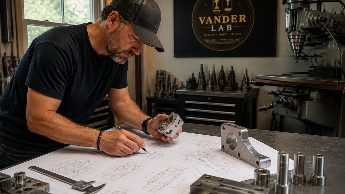
Good mechanical design accounts for how components fit, move, and support loads, where most amateur designs fail despite looking right on screen.
Think about three core principles:
Mechanical advantage and load paths. Stress concentrates at joints; a sharp corner fails faster than a rounded one, and a thicker wall in the right spot carries more load than extra material scattered everywhere.
Clearance and interference. A spinning shaft needs clearance; a press-fit bearing needs just enough interference to stay put without cracking.
Symmetry and balance. Uneven wall thickness causes warping in 3D printing; symmetrical designs cost less because machines cut them more efficiently.
Start by asking: What is this part supposed to do? Does it hold weight? Does it move? Does it connect to other parts?
CNC Machining Design Guidelines and Best Practices
A CNC router can't cut a hole smaller than its smallest tool or an internal corner sharper than the tool radius. Understanding these constraints shapes your design.
Here are the key rules for CNC machining design:
- Tool access matters. Plan tool paths before finalizing your design; deep pockets need long tools, narrow slots need narrow tools.
- Avoid sharp internal corners. CNC tools are round; plan for hand finishing if you need sharp corners.
- Keep walls thick enough. Keep walls thick enough.
- Design for chip clearance. Avoid dead-end pockets; deep pockets need manual cleanup.
- Use standard tool sizes. Design around common end mills (1/8, 1/4, 3/8, 1/2 inch) to avoid custom tool costs.
Use CNC for precision and complex shapes; laser cutting is faster and cheaper for simple flat cuts.
Designing for CNC Tolerances and Precision
Tolerance is how close your finished part matches your drawing.
How Tolerance Affects Cost and Lead Time
Tighter tolerances require extra steps, which can affect lead time. Understand these trade-offs before specifying.
Specifying Tolerance by Feature Type
Specify tight tolerance only where it matters functionally.
The Over-Specification Trap
Marking everything ±0.001 inch wastes money on precision you don't need.
Stack-Up Tolerance and Assembly Clearance
When multiple parts fit together, tolerances add up.
Bilateral vs. Unilateral Tolerance
Bilateral (±) tolerance varies equally above and below nominal; unilateral (+/−) varies more in one direction.
Geometric Tolerance vs. Dimensional Tolerance
Dimensional tolerance controls size; geometric tolerance controls shape (flatness, perpendicularity, runout, concentricity) and costs more.
Communicating Tolerance to Your Fabricator
Before sending your design, ask your fabricator: What tolerance can you hold without secondary finishing? What requires hand finishing?
Choosing CAD Software for CNC Parts
Choose CAD software based on complexity and export needs. FreeCAD (free, 3D modeling) works for most projects. Fusion 360 (cloud-based, CAM tools) suits makers. SolidWorks (industry standard) handles complex assemblies. Inkscape (free vector software) works for flat designs. Ask your fabricator which file format they prefer before starting.
How to Prepare Files for CNC Routing and 3D Printing
Before a machine can cut or print your part, the file must be prepared correctly. Bad file preparation causes failed prints, broken tools, and wasted material.
Understanding File Formats and When to Use Each
DXF is standard for 2D cutting (laser, plasma, waterjet); it's vector-based and scales infinitely.
Exporting Correctly from Common CAD Software
Fusion 360: Use File > Export; verify unit settings (Fusion defaults to millimeters). FreeCAD: Use File > Export As; set document units before exporting.
Critical Pre-Submission Checks
Before you send a file to your fabricator, run through this checklist:
-
Verify units. Open your exported file in a free viewer (Fusion 360 Viewer, FreeCAD, or an online STEP viewer). Measure a known dimension, a 1-inch line should be 1 inch. A unit mismatch scales your entire part by 25.4× (millimeters to inches) or 1/25.4× (inches to millimeters). This is the most common file error and the hardest to catch after fabrication starts.
-
Check for gaps and overlaps in 2D profiles. If you're exporting DXF for laser or CNC cutting, zoom in on corners and intersections. Open lines or overlapping segments cause the machine to pause, restart, or cut incorrectly. Use your CAD software's "Check" or "Validate" tool, or ask your fabricator to review the file before cutting.
-
Confirm wall thickness for 3D printing. Most 3D printers require minimum wall thickness of 0.8-1.5 mm depending on the material and printer. Thinner walls fail during printing or snap during removal. Use your CAD software's thickness analysis tool (Fusion 360 has a "Thin Wall" check under Design > Analyze) to flag problem areas.
-
Test the file in the fabricator's software. If possible, ask your shop to import your file and show you a preview before they commit to cutting or printing. Many shops offer this as a standard step. A 5-minute preview catches 90% of file errors.
-
Include a scale reference. Add a 1-inch or 10-mm line somewhere on your drawing as a reference. Your fabricator can verify that the file imported at the correct scale.
-
Document your tolerances and material. Include a note in your file or cover email specifying:
- Material (aluminum, acrylic, PLA, etc.)
- Required tolerances (e.g., "±0.005 inch on mating surfaces")
- Surface finish (as-cut, sanded, polished)
- Any special handling (fragile, heat-sensitive, etc.)
Common File Preparation Mistakes and How to Avoid Them
- Submitting a PDF or image instead of a CAD file. Machines can't read PDFs or JPEGs. Always send the native file format (DXF, STEP, STL) or ask your fabricator which format they prefer.
- Forgetting to convert text to outlines in vector files. If you're sending a DXF for laser engraving and you leave text as editable text, the fabricator's software may substitute a different font. Convert all text to paths or outlines before exporting.
- Designing in the wrong plane. If your DXF is drawn on the wrong layer or plane, the laser or CNC may cut nothing or cut the wrong geometry. Verify that your 2D profile is on the XY plane (the cutting plane) before exporting.
- Ignoring layer organization. If you're sending a complex DXF with multiple layers, label them clearly ("Cut," "Engrave," "Score"). Fabricators use layers to assign different operations to different tools.
- Exporting at the wrong resolution for STL. Exporting at the wrong resolution for STL can lead to issues. Check your CAD software's STL export settings and ask your printer for their preferred resolution.
Working with Your Fabricator on File Review
The best file preparation is a conversation. Before you finalize your design, ask your fabricator:
- What file format do you prefer?
- What unit system do you work in (inches or millimeters)?
- Do you want me to include tolerances in the file, or should I specify them separately?
- Can you review my file before I commit to a full run?
A quick file review catches problems that would otherwise waste material and time. If your design needs adjustment for manufacturability, a good fabricator will walk you through it.
Design Review and Prototyping Before Fabrication
Before you commit to a full production run, test your design with a prototype. This catches problems that CAD can't show you.
A design review should ask:
- Does it fit? Assemble the prototype with surrounding parts. Does everything line up? Are there interferences you missed?
- Does it function? If your part moves or carries load, test it. A design that looks right might bind or flex too much.
- Can it be manufactured? Build the prototype using the same process you'll use for production. If you're using 3D printing, print the prototype. If it's CNC, machine it. This reveals fabrication problems early.
- Is it over-designed? Prototyping shows where you added extra material you don't need. Removing it saves cost and weight.
Iteration is normal. Most successful parts go through three to five design cycles. Each cycle teaches you something the previous version missed.
Prototyping is often the first step when working with a fabricator. A rough sketch can become a printed prototype in days. That prototype tells you whether your concept actually works before you invest in tooling or production.
Designing machine-ready parts takes practice, but the fundamentals are learnable. Start with simple projects, a small bracket, an engraved sign, a custom holder. Each project teaches you how machines think and what fabricators actually need. When you're ready to move from concept to finished part, Custom Quotes can help you turn your design into precision-built reality. We work from sketches, photos, or finished CAD files, and we'll guide you through the design process if your drawing needs refinement. You can also browse completed work and explore options through our Ebay Shop to see the range of what's possible.
Frequently Asked Questions
What's the difference between a sketch and a machine-ready part design?
A sketch captures your idea in rough form, dimensions might be approximate, details unclear. A machine-ready design includes precise dimensioning, tolerances, material specifications, and fabrication notes that a CNC machine or 3D printer can execute without guesswork. Machine-ready files are drawn to exact specifications so the final part meets your requirements every time.
How tight should tolerances be when designing for CNC machining?
Tolerance depends on your part's function. Functional parts that fit together need tighter tolerances. Specify only the precision you actually need, tighter tolerances cost more and take longer to machine. Your fabricator can advise on what's realistic for your material and design.
Can I design parts in any CAD software, or does it matter which one I use?
Most CAD software can export to formats your fabricator accepts (STEP, IGES, STL). What matters is that you create accurate, dimensioned drawings with clear specifications. Free tools like Fusion 360 or FreeCAD work well for custom parts. The key is learning to dimension properly, define tolerances, and export in a format your fabricator requests, not the software itself.
What happens if my design isn't ready for fabrication?
An incomplete design can lead to delays, costly mistakes, or parts that don't work as intended. Before sending files to fabrication, check that all dimensions are specified, tolerances are defined, materials are noted, and assembly details are clear. A design review with your fabricator catches issues early, they can spot undercuts, wall thickness problems, or assembly challenges you might miss, saving time and money.