 how-to
How to Prepare Files for Industrial 3D Printing
Last Updated: November 6, 2026
Quick Summary
To prepare files for industrial 3d printing, export the right format for your process, confirm units and scale, and make the mesh watertight and manifold. Then repair geometry, add process-specific features like escape and drain holes, and run a preflight check before handoff.
- STL carries geometry only, 3MF adds units and materials, and STEP preserves exact CAD surfaces.
- A part modeled in millimeters and imported as inches comes out 25.4 times too large, and the slicer won't warn you.
- Aim for the coarsest mesh that still holds your tolerances rather than exporting at maximum resolution.
- SLS and MJF parts need escape holes a few millimeters in diameter so unfused powder can drain.
- Send the file, drawing, material, and orientation together, since vague handoffs cost days.
Table of Contents
- What You'll Need Before You Export a Print-Ready File
- Step 1: Export the Right File Format From Your CAD Model
- Step 2: Set Units and Check Model Scale
- Step 3: Inspect Mesh Quality, Resolution, and Polygon Count
- Step 4: Make the Mesh Watertight and Manifold
- Step 5: Run 3D Model Repair for Manufacturing
- Industrial 3D Printing File Requirements Most Hobby Guides Skip
- Common Mistakes to Avoid Before You Send the File
- Frequently Asked Questions
What You'll Need Before You Export a Print-Ready File
Learning how to prepare files for industrial 3D printing starts with one shift in mindset: the file is a manufacturing document, not a picture. At VanderLab, we treat every export as a handoff to a machine that will follow it exactly, flaws and all. The standards bar keeps rising as industrial 3D printing grows.
Before you export, gather four things:
- A finished CAD model with all features modeled, not faked with textures
- The material and process your print shop will run
- A unit and tolerance standard agreed with that shop
- A naming and revision convention for the file itself
Material choice shapes file prep more than most people expect. Our guide to the best 3D printing materials for functional parts covers how PLA, PETG, ABS, and metals differ.
Step 1: Export the Right File Format From Your CAD Model
The right export format depends on the process. STL is universal but carries geometry only. 3MF carries units, materials, and color. STEP preserves exact CAD surfaces for machining and engineering review.
Here's the short version: STL for simple prints, 3MF for production runs, STEP when the shop needs the real model.
STL, 3MF, or STEP: Which Export Wins
| Format | Carries | Best For | Watch Out |
|---|---|---|---|
| STL | Triangles only | Quick prototypes | No units, no material data |
| 3MF | Mesh, units, color | Production batches | Some older slicers ignore it |
| STEP | Exact surfaces | Engineering handoff, CNC | Needs a real CAD kernel |
Apply all features before you export, since an STL from a model with unapplied construction history can be misleading.
Step 2: Set Units and Check Model Scale
Unit errors are the most expensive mistake in file prep. A part modeled in millimeters and imported as inches comes out 25.4 times too large. The slicer won't warn you. It will just build the wrong part.
Check scale before anything else:
- Confirm your CAD file's unit setting
- Measure one known dimension against the drawing
- Import into the slicer and re-measure
- Compare against the build volume
If dimensions come out wrong, our walkthrough on fixing custom part dimensions covers the usual culprits, from unit mismatches to scaled assemblies.
Step 3: Inspect Mesh Quality, Resolution, and Polygon Count
Mesh quality decides whether your part prints clean or fails halfway. Resolution and polygon count sit on a trade-off: more triangles mean smoother curves but bigger files and slower slicing.
Aim for the coarsest mesh that still holds your tolerances. Exporting at maximum resolution "just in case" creates huge files without better parts. For load-bearing components, pair mesh inspection with our guide to designing 3D parts for structural strength.
Look for these before you move on:
- Faceting on curved surfaces
- Thin features that lost triangles
- Spikes or stray triangles from bad booleans
- Polygon count that seems wildly high or low
Step 4: Make the Mesh Watertight and Manifold
A watertight mesh has no holes. A manifold mesh has every edge shared by exactly two faces. Both matter because slicers need closed, predictable geometry to generate toolpaths.
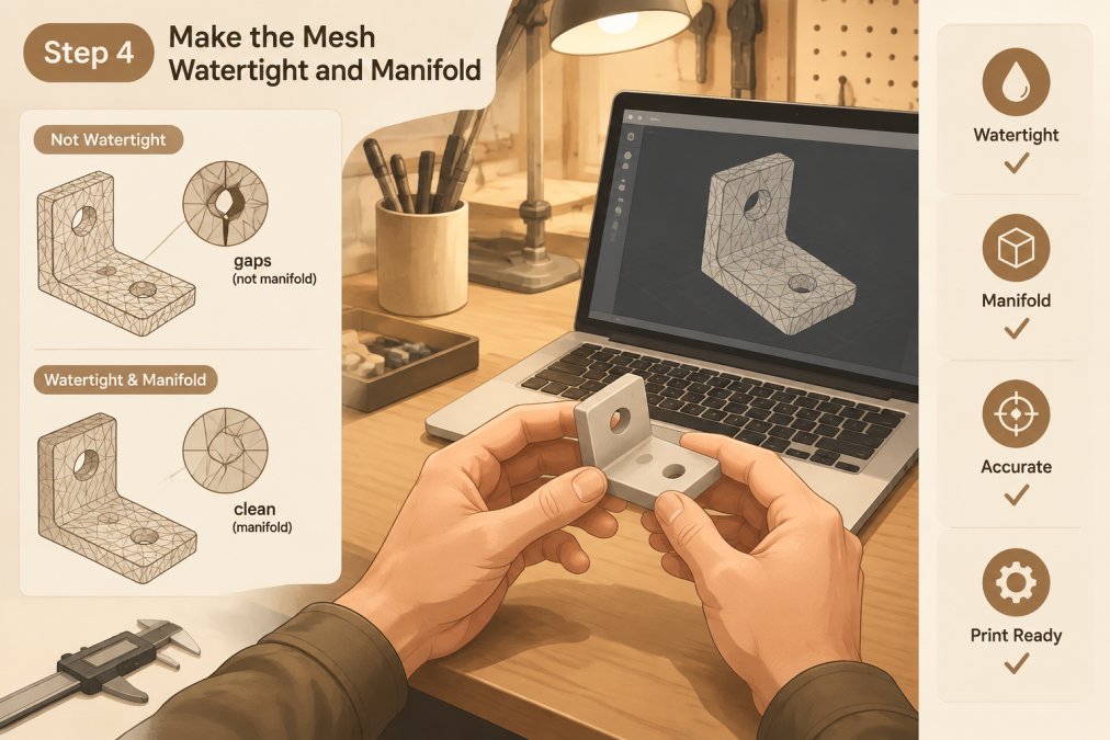
Open edges, flipped normals, and non-manifold edges all cause the same result: the slicer guesses, and the guess is usually wrong. Run a mesh check in your CAD tool or slicer before export.
Step 5: Run 3D Model Repair for Manufacturing
3D model repair for manufacturing goes further than a hobby fix. It means correcting geometry so the part meets the process, not just closing holes. The goal is a file that passes a repeatable preflight, not one that merely looks right on screen.
Repair in this order:
- Heal open edges and non-manifold geometry
- Remove internal shells and duplicate faces
- Re-check wall thickness against the process minimum
- Re-verify units and overall dimensions
- Save a clean revision and log the changes
Automated repair tools save time, but check their output, since some fill holes in ways that change the part's function.
A Preflight Checklist With Measurable Checks
Before a file leaves your hands, run it against a short list of pass/fail checks. Most shops will run their own version of this, and a file that arrives already passing saves a round trip:
- Units and scale: one known dimension measured against the drawing, confirmed in both CAD and the slicer
- Mesh closure: zero open edges, zero non-manifold edges, normals pointing outward
- Wall thickness: every wall at or above the process minimum, checked on the thinnest feature, not the average
- Feature size: smallest hole, slot, and pin diameter above the process floor
- Escape and drain holes: present for powder-bed and resin processes, sized and placed per the shop's guidance
- Orientation and supports: orientation noted, support strategy agreed, cosmetic faces flagged
- File naming and revision: part number, revision letter, material, and process in the filename
- Deliverables: mesh file, native CAD or STEP where requested, drawing, and material spec sent together
Automated Validation and Acceptance Criteria
Quoting and repair tools can catch a lot of this automatically. Many service bureaus run an upload through an automated check that flags non-manifold geometry, wall thickness below the process minimum, and parts that exceed the build volume.
A common pattern is to define acceptance criteria up front with the shop: which checks must pass, what tolerance the drawing calls out, and who owns the fix if a check fails. That agreement is what separates a production handoff from a hopeful email attachment.
Watch out: automated repair can silently change a critical dimension, so always re-measure one known feature after running it and compare against the drawing before you send the file.
Industrial 3D Printing File Requirements Most Hobby Guides Skip
Hobby guides stop at "watertight and manifold." Industrial 3D printing file requirements go further, because the file now feeds a production process with real cost and lead time attached. The same STL that prints fine on a desktop machine can trap powder in an SLS build, leave uncured resin in an SLA part, or warp off a metal build plate. Preparation has to match the process, not just the mesh.
More machines mean more handoffs, and more handoffs mean the file has to speak for itself.
Process-Specific File Constraints
Each industrial process imposes its own geometry rules before the file ever reaches the machine:
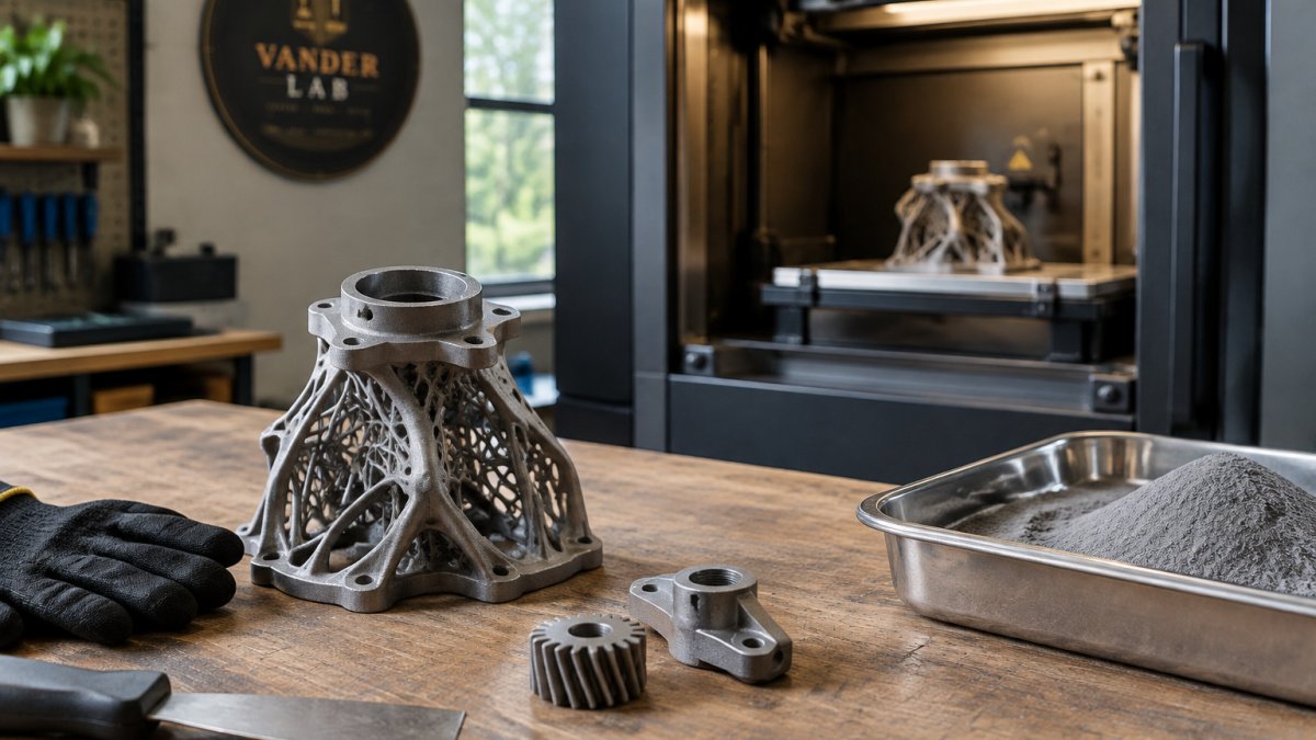
- SLS and MJF (powder bed, polymer): Parts need escape holes so unfused powder can drain, typically a few millimeters in diameter and placed in hidden or non-cosmetic areas. Minimum wall thickness usually runs around 0.8-1.0 mm for SLS and slightly thicker for MJF, and thin fins or tall unsupported walls are prone to warping. Nesting matters because powder-bed builds are priced by volume, not by part count.
- SLA and DLP (resin): Hollowed parts need drain holes in at least two locations so resin can escape and air can enter, and trapped resin left inside will cure into a blob. Minimum feature size is finer than powder bed, but thin walls below roughly 0.5 mm can curl, and supports must be modeled or generated with post-processing access in mind.
- Metal powder-bed fusion (DMLS, SLM): Support structures are mandatory and are part of the file, not an afterthought. Parts need escape holes for trapped powder, orientation is chosen to limit overhangs and residual stress, and build-plate adhesion features are often added. Design rules for minimum wall, overhang angle, and hole diameter are stricter than polymer processes.
- FDM and large-format polymer: Minimum wall is driven by nozzle diameter, and orientation determines where layer lines and supports land. Long thin parts need orientation chosen to keep the strong axis along the load.
A common pattern is a customer sending a watertight STL that is still unbuildable because it has no escape holes, a wall below the process minimum, or a trapped internal cavity. Those are design-for-additive-manufacturing problems, not mesh problems, and they are the ones hobby guides skip.
Build-Volume Packing and Production Orientation
Orientation affects strength, surface finish, supports, build time, and cost. Decide it before you send the file, not after. Pack parts to fit the build volume with clearance for supports, and note the orientation in your handoff.
On a powder-bed or resin machine, the build is a shared resource. Nesting parts tightly raises throughput but can crowd supports and make post-processing harder; spacing them out costs build volume but protects finish.
Watch out: a part oriented for the fastest print is often the part that needs the most support removal and the most finishing, which quietly raises cost even when build time drops.
Engineering Handoff and File Validation
Validation means proving the file is buildable before the machine starts. Send a drawing, a revision number, and the material spec together. If your part is metal, our overview of what to know before ordering a metal 3D print covers what shops check first.
Common Mistakes to Avoid Before You Send the File
Most rejected files fail for boring reasons. Here are the ones we see and hear about most:
- Exporting before applying all CAD features
- Skipping the unit check
- Sending an STL when the shop asked for STEP
- Forgetting to name the revision
- Assuming the shop will "just fix it"
Watch out: vague handoffs cost days. Send the file, the drawing, the material, and the orientation together. If timing matters, read up on turnaround time for custom 3D printed parts before you promise a date to anyone.
File prep is where good ideas either become real parts or stall in a folder. If you'd rather hand the whole thing to a maker, VanderLab offers CAD design, 3D printing, and CNC machining from our Mebane shop, with local pickup and shipping available. Send us a sketch or a rough idea through our Custom Quotes form, and we'll work with you on a finished part.
Frequently Asked Questions
What are the most common file formats for industrial 3D printing?
STL is the most widely accepted format because nearly every slicer reads it, but it stores geometry only, no units or color. 3MF carries units, materials, and multiple bodies, which makes it a better fit for industrial workflows. STEP is preferred when the shop needs to re-tolerance or modify the model. Ask your fabricator which format they want before exporting, since converting after the fact can lose detail.
How do you ensure a 3D model is watertight for industrial printing?
A watertight mesh has no holes, no flipped normals, and no non-manifold edges where more than two faces share one edge. Run a mesh analysis in your CAD or repair tool to flag open edges, then close them manually or with an automatic repair pass. Check again after repair, because automated fixes can create new self-intersections. A watertight model lets the slicer calculate inside and outside cleanly, which prevents failed walls and supports.
What is the difference between hobbyist and industrial 3D print file preparation?
Hobbyist prep often stops at a quick STL export and a visual check in the slicer. Industrial 3D printing file requirements add validation steps: documented units, verified wall thickness and minimum feature size, orientation chosen for the process and material, packing across the build volume, and a handoff record the shop can trace. The geometry may be identical, but the checks and documentation are not.
How do you check wall thickness and tolerance in 3D print files?
Most CAD packages include a thickness analysis tool that highlights regions thinner than a value you set. Compare those results against the minimum your process and material can hold, and thicken anything that falls short before export. For tolerance, model clearance between mating parts explicitly rather than relying on the printer to hit nominal dimensions. Confirm both again in the sliced preview, where thin walls show up as gaps or single-pass lines.