 how-to
Custom Part Dimensions Wrong? How to Fix Them
Table of Contents
- Start With Measurement: How to Measure Custom Parts for Accuracy
- Was the Error in the CAD File or the Machine? A Diagnostic Workflow
- CNC Machining Tolerance Standards: What Your Part Should Actually Hold
- Common Causes: Over-Extrusion, Shrinkage, and Thermal Expansion
- Communicating With Custom Fabricators About Defects
- Fix It or Remake It? A Decision Matrix for Remediation
- When Custom Part Dimensions Keep Coming Out Wrong: Prevention Checklist
- Frequently Asked Questions
Last Updated: September 27, 2026
Start With Measurement: How to Measure Custom Parts for Accuracy
When custom part dimensions come out wrong, the first question isn't who to blame, it's whether the measurement itself is trustworthy. This guide covers the tools and habits that give you numbers you can defend.
Tools That Give You Numbers You Can Trust
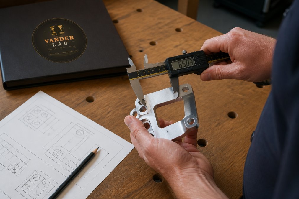
- Digital calipers: good for outer, inner, and depth reads
- Micrometers: better for round features and thin walls
- Height gauges: for flatness and step checks
- Pin gauges: for hole diameters
- CMM or optical comparators: for complex geometry
Temperature, Technique, and Other Silent Error Sources
Metal moves with heat. A part measured off a warm machine can read differently once it cools.
- Let parts reach room temperature before final checks
- Hold calipers by the body, not the jaws
- Keep the part square to the jaws
- Zero the tool before every session
- Avoid measuring over burrs or chips
These habits separate a reliable reading from a guess.
Was the Error in the CAD File or the Machine? A Diagnostic Workflow
The fastest way to fix a wrong part is to find where the error entered the process. A simple workflow narrows it to three suspects: the CAD file, the machine, or the material. Work through them in order.
Validating Your STL File Integrity and CAD Drawing
An STL file is a mesh, not a solid model. If it isn't water-tight, the slicer or CAM software can misread it.
- Check for gaps, flipped normals, and open edges
- Compare the STL against the original CAD drawing
- Confirm units (inches vs. millimeters) before export
- Verify the scaling factor wasn't changed
Troubleshooting CNC Dimensional Errors on the Machine Side
If the file is clean, look at the machine. CNC dimensional errors trace back to a handful of causes.
- Loose tooling: a slipping collet changes depth mid-cut
- Worn bits: dull cutters push material instead of slicing it
- Backlash: play in the X/Y axis throws off position
- Steps per mm: wrong values scale every move
- Workholding: a part that shifts ruins every dimension
CNC Machining Tolerance Standards: What Your Part Should Actually Hold
Not every dimension needs to be perfect. Tolerance standards exist so you know what's realistic before you order, and so your fabricator knows where to spend effort and where to save it. Tighter tolerances often require slower feeds, better tooling, more inspection, and sometimes a different process.
| Feature Type | Typical Tolerance | Notes |
|---|---|---|
| General dimensions | +/- 0.005 in | Standard shop default |
| Hole diameters | +/- 0.002 in | Depends on drill vs. ream |
| Flatness | 0.003 in | Affected by workholding |
| 3D printed parts | +/- 0.010 in | Varies by material |
| Press-fit bores | +/- 0.0005 in | Usually requires reaming |
Where Those Numbers Come From
Tolerance isn't a guess. It's the sum of everything that can move a cut off target:
- Machine positioning error, the difference between where the controller thinks the tool is and where it actually is
- Tool deflection, a long, thin end mill bends under cutting force, so the wall it leaves behind is thinner than programmed
- Thermal growth, a spindle that warms up during a long run drifts, which is why the first part and the fiftieth part can differ
- Workholding shift, a part that creeps in the vise loses its datum, and every downstream dimension inherits the error
- Material behavior, aluminum moves differently than steel, and both move differently than ABS or PLA
Tolerance Stack-Up: Why One Tight Callout Can Sink a Part
A single tight dimension is manageable. A chain of them is not.
A few habits keep stack-up from biting you:
- Tighten only what functions. If a hole locates a bearing, hold it tight. If a hole just passes a wire, leave it at general tolerance.
- Use a datum. Dimension from one reference feature instead of chaining from feature to feature.
- Ask about capability, not just tolerance. A shop can hit +/- 0.001 inches on a lathe and struggle with the same number on a mill. Match the callout to the process.
- Call out the fit, not just the size. A shaft that needs to slide into a bore has a fit requirement, and the fit is what matters, not the individual numbers.
Matching Tolerance to Method
Different processes hold different bands, and no drawing detail changes that:
- CNC milling and turning, tightest general work, best for functional parts
- CNC routing, great for flat parts and signage, looser on Z-depth
- Laser cutting, excellent on profile, limited on thickness
- 3D printing, widest band, best for prototypes and non-critical fits
- Hand finishing, can tighten a feature after the fact, but only if there's material to remove
Common Causes: Over-Extrusion, Shrinkage, and Thermal Expansion
Printed and machined parts fail for different reasons. Knowing which one you're dealing with saves time.
Fixes vary by cause:
- Over-extrusion: lower flow rate, recalibrate steps per mm
- Shrinkage: apply a scaling factor in the slicer, adjust cooling
- Thermal expansion: measure at a consistent temperature
Communicating With Custom Fabricators About Defects
How you raise a problem decides how fast it gets solved. Communicating with custom fabricators about defects works best when you bring evidence, not frustration.
Start with facts:
- Which dimensions are off, and by how much
- What the drawing specified
- How you measured, and with what tool
- Photos of the part and the measurement
- The revision number of the drawing you ordered from
Documentation for Quality Claims and Dispute Resolution
A clean paper trail turns a dispute into a fix, and decides who eats the cost.
Keep these on hand:
- The original CAD drawing and revision number. If the drawing changed after the order, say so up front. Revision mismatches cause more disputes than bad machining.
- The purchase order and agreed tolerances. If tolerances were discussed in email, that email is part of the contract.
- Your measurement records with dates. Note the tool used, the temperature, and the number of readings.
- Photos and notes from first-article inspection. A photo of the caliper jaw on the feature, with the reading visible, is worth more than a paragraph of description.
- A short written summary of the discrepancy. One page, one table: feature, specified, measured, difference.
How a Non-Conformance Report Works
In manufacturing, a formal quality complaint is called a non-conformance report, or NCR. The ASQ quality resources on non-conformance explain the general structure. The version you send to a fabricator doesn't need to be formal, it needs to be complete.
A workable NCR has five parts:
- Identification, part number, revision, order number, date received
- Description of the discrepancy, what was specified versus what was measured
- Evidence, measurements, photos, inspection notes
- Impact, can the part be used, reworked, or must it be remade?
- Requested resolution, replacement, rework, credit, or a conversation
What to Do When the Shop Pushes Back
Sometimes the fabricator disagrees. That's normal, and it usually comes down to one of three things:
- Measurement disagreement. Your caliper and their CMM read differently. Ask what they measured with and how. A shared reference, a pin gauge, a certified standard, often settles it.
- Drawing ambiguity. The feature was dimensioned in a way that allowed two readings. This is a design problem, not a fabrication problem, and it's worth fixing in the file before the next run.
- Tolerance mismatch. The drawing called for something the process can't hold. If that wasn't flagged at quote time, it's a conversation about who should have caught it.
Fix It or Remake It? A Decision Matrix for Remediation
Not every wrong part needs a remake. Sometimes a small post-processing fix saves the job.
| Situation | Best Move | Why |
|---|---|---|
| Dimension off by a hair, non-critical | Post-process (sanding, reaming) | Cheapest, fastest fix |
| Critical feature out of tolerance | Remake the part | Can't risk function |
| Error in the CAD file | Fix file, re-run | Machine was fine |
| Supplier error, documented | File a claim | You have the evidence |
| Repeated error on same feature | Re-calibrate machine | Root cause is the setup |
When Custom Part Dimensions Keep Coming Out Wrong: Prevention Checklist
Repeat failures point to a process gap, not bad luck. Use this checklist before every run.
- Confirm units in the CAD file before export
- Validate the STL is water-tight
- Calibrate the machine and check steps per mm
- Run a first-article inspection
- Measure at a consistent temperature
- Document every measurement
- Agree on tolerances in writing before ordering
- Keep a log of past errors and fixes
Frequently Asked Questions
Why is my custom-fabricated part coming out with the wrong dimensions?
Dimensional errors usually trace back to one of three places: the design file, the machine setup, or the material. A CAD drawing with conflicting tolerances, an STL file that isn't water-tight, or a slicer scaling factor set incorrectly will all produce a wrong-sized part. On the machine side, loose belts, worn lead screws, or steps per mm that need re-calibration cause consistent offsets. Material shrinkage during cooling or thermal expansion in the shop adds another layer. Measuring your part carefully and comparing it to the original CAD drawing tells you which category you're dealing with.
How do I verify if a dimensional error is in the CAD file or the machine setup?
Print or machine a simple calibration cube or test coupon with known dimensions. Measure it with calipers. If the test piece is accurate but your actual part is not, the problem is in the CAD file or how the slicer interpreted it. If the test piece is also off by the same amount, the issue is in the machine: steps per mm, belt tension, or backlash. This first-article inspection approach isolates the source before you spend time re-calibrating or re-drawing anything.
Can material shrinkage or expansion affect custom part dimensions?
Yes, and it's one of the most overlooked causes. ABS can shrink up to 0.8% as it cools, which on a 200 mm part means a 1.6 mm shortfall. Nylon and polypropylene shrink even more. Metals expand and contract with temperature too, so a part measured right off a warm CNC bed may read differently once it reaches room temperature. If your CAD drawing specifies a tight tolerance, ask your fabricator what scaling factor they apply for the material and whether they measure after the part has fully cooled.
How should I communicate dimensional discrepancies to a fabrication partner?
Lead with data, not frustration. Photograph the part next to your measurement tool showing the actual reading. Reference the specific dimension on the technical drawing that's out of spec, and state the measured value versus the nominal value. Note whether the error is consistent across multiple parts or a one-off. If you have a first-article inspection report, include it. Most fabricators, including small shops, will re-calibrate and re-run the job when they can see exactly what went wrong and where.