 ultimate-guide
Why Professional CAD Design Is Essential for Custom Parts
Table of Contents
- Why Professional CAD Design Is Essential for Custom Fabrication
- From a Sketch on Paper to a File a Machine Can Cut
- What Changes When a Designer Builds the Model
- How Professional CAD Design Improves Accuracy and Fit
- CAD Design Best Practices That Keep Projects on Track
- Tools for Professional CAD Design and When Each One Fits
- Where CAD Saves Money, Time, and Material
- AI, Cloud Collaboration, and What Comes Next
- Conclusion
- Frequently Asked Questions
Last Updated: September 22, 2026
Why Professional CAD Design Is Essential for Custom Fabrication
A part that looks right on a napkin sketch can still fail on the shop floor. At VanderLab, the difference between a rough idea and a built-to-spec part comes down to the model underneath it. This guide explains why professional CAD design is essential from first sketch to final cut.
From a Sketch on Paper to a File a Machine Can Cut
Computer-aided design (CAD) is the process of building a precise digital model of a part before anything is physically made. That model becomes the single source of truth for the whole project, from the first concept to the final inspection.
- Every dimension is defined and driven, not estimated
- Tolerances are assigned to the features that actually need them
- The part is checked for design feasibility before tooling is set up
- The file exports cleanly to whatever the machine expects
What Changes When a Designer Builds the Model
A designer does more than trace a sketch. They interrogate it: Where does this part meet another? Which surface carries load? Which dimension can drift without breaking the assembly?
How Professional CAD Design Improves Accuracy and Fit
Tolerances, Interference, and Assembly Design
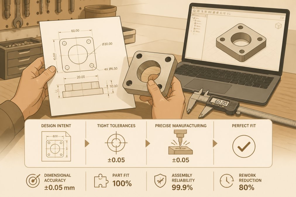
Tolerance is the allowable variation on a dimension. Too loose and parts rattle or leak; too tight and the part becomes expensive or impossible to produce. A professional designer knows which features need tight tolerances and documents that in the drawing.
Catching Problems Before the First Cut
This is the quiet advantage of modeling up front. A designer can run an iteration entirely on screen, change a wall thickness, re-run a simulation, check the fit. No material is consumed, no machine time is spent, and no one waits on a physical part to learn whether an idea works.
CAD Design Best Practices That Keep Projects on Track
Good CAD design best practices are less about software than discipline. Most failed custom projects trace back to a skipped step, not a bad tool.
- Model to the manufacturing method. A part destined for 3D printing and one for CNC routing need different geometry. Prints need chamfered edges and minimum wall thicknesses to avoid warping; CNC-routed parts need radii at inside corners sized to the cutter, because a square internal corner cannot be milled without a specialty tool.
- Keep version control honest. Name revisions clearly and archive old ones. A simple convention, part name, revision letter, date, means the file on the machine matches the file on the drawing.
- Use drafting standards consistently. A drawing any shop can read correctly beats a clever one only you understand. Following a recognized dimensioning and tolerance convention lets a second fabricator pick up the job without a phone call.
- Document intent, not just dimensions. Note which surfaces matter and why. A tolerance with no stated reason invites a machinist to guess, and guesses are where fit problems start.
- Review the model before release. A five-minute check beats a scrapped batch. Look for unconstrained sketches, duplicate geometry, and features referencing a deleted face, the three most common causes of a model that looks fine and cuts wrong.
The File Format Question Nobody Asks Early Enough
Most custom projects touch more than one piece of software before they touch a machine. A model built in one parametric program often has to open in a CAM package, a slicer, or a laser cutter's control software. That handoff is where geometry quietly breaks.
A few habits prevent most of it:
- Export a neutral format alongside the native file. A STEP file carries solid geometry between systems without the feature history only the original program understands.
- Check the mesh before printing. STL and similar formats approximate curved surfaces with triangles. Too coarse and a round hole becomes a polygon; too fine and the file becomes unwieldy.
- Keep the native file, not just the export. The neutral format is for the machine. The native file is for the next revision, and it is the only one that lets you change a dimension without rebuilding from scratch.
Where Discipline Pays Off on a Real Project
Consider a simple engraved address sign. It sounds like a one-step job, but the model has to account for mounting holes lining up with studs or siding, engraving depth clearing the material's surface finish, and lettering staying legible after the cut. A designer who models to the material and mounting method catches all three before the router starts.
A Framework for Deciding When Professional CAD Pays Off
Not every project needs the same modeling rigor, and part of professional judgment is knowing where to spend the effort. Weigh three factors: how many parts must fit together, how tight the tolerances are, and how expensive the material or machine time is to redo.
- A single decorative piece in a forgiving material can be modeled quickly, because a small error is cosmetic rather than functional.
- A multi-part assembly, or anything with a moving interface, rewards full parametric modeling and an interference check, because a fit error compounds across every part.
- Anything cut from expensive stock or run on a machine with long setup times justifies simulation and a feasibility review, because a failed first attempt is costly.
Tools for Professional CAD Design and When Each One Fits
Choosing tools for professional CAD design comes down to what you are making and who has to open the file afterward.
| Tool Type | Best For | Typical Strength | Watch Out For |
|---|---|---|---|
| Parametric modelers | Mechanical parts, assemblies | Edits propagate cleanly | Steeper learning curve |
| Direct modelers | Quick concept work, organic shapes | Fast to start | Weaker history tracking |
| Mesh-based tools | Sculptural and decorative pieces | Freedom of form | Harder to dimension precisely |
| Cloud-based platforms | Distributed teams | Easy collaboration tools | Data security questions |
Where CAD Saves Money, Time, and Material
Savings from professional CAD design show up in three places, none of them the invoice for the modeling itself.
AI, Cloud Collaboration, and What Comes Next
Most ranking articles still explain CAD as if it were a drafting tool with a 3D view. The technology has moved. Understanding where it is going is part of understanding why professional design matters now.
Generative Design: From Drawing Geometry to Judging It
Generative design flips the usual workflow. Instead of drawing a shape and testing whether it holds up, the designer sets the constraints, load points, mounting locations, material, weight target, and the software proposes geometries that satisfy them. The output often looks organic, because the algorithm removes material wherever it is not needed to carry load.
Digital Twins: The Model That Outlives the Build
A digital twin is a model kept in sync with a physical part, so the file remains a live record rather than a one-time drawing. For custom work, the benefit is simpler than the industrial version: the file you keep becomes the record of what was actually built. If a part needs to be reordered, repaired, or modified years later, the model is the starting point instead of a fresh measurement.
Cloud Collaboration and the IP Question
Cloud-based design has changed how teams share work, and it raises a real question about where proprietary files live and who can access them. For a business handing over a design that represents real investment, that question is not abstract.
- Know where the file is stored and who administers the account. Access control is only as good as the account behind it.
- Share exports rather than source files when a collaborator only needs to view or cut. A STEP file communicates geometry without handing over the editable history.
- Keep an offline copy of anything you cannot afford to lose or leak. Local backups remain the simplest form of control.
What Has Not Changed
AI can generate options. Cloud tools can move them around the world. What has not changed is the need for judgment, deciding which option is manufacturable, affordable, and right for the job. That decision is still professional work, and still the reason a trained designer matters more, not less, as the tools get more capable.
Conclusion
Custom fabrication rewards preparation. The projects that go smoothly are the ones where the model was right before the machine ever started. That is the case for professional CAD design, and the standard we hold at VanderLab.
Frequently Asked Questions
What are the primary benefits of using professional CAD design for custom fabrication?
Professional CAD design turns a rough idea into a file a machine can actually cut or print. That means fewer surprises on the shop floor: dimensions match, parts fit together, and the design can be checked for weak spots before anything is made. It also cuts wasted material and shortens the back-and-forth between an idea and a finished piece. For one-off commissions and small production runs alike, that precision is what separates a part that works from one that gets remade.
How does professional CAD design improve the accuracy of 3D printed parts?
A well-built model accounts for how a printer actually behaves, not just how the part looks on screen. Wall thickness, clearances, and orientation all get set in the file, so the printed result matches the design instead of drifting off spec. With 3D modeling and simulation built in, you can test fit and function digitally before committing filament. The result is parts that assemble the first time, whether you need one prototype or a batch for an event.
What is the difference between amateur sketching and professional CAD modeling?
A sketch communicates an idea. A CAD model defines it precisely enough to manufacture. Professional modeling captures exact dimensions, tolerances, and assembly relationships, and it produces technical drawings and manufacturing specifications a machinist or printer can follow without guessing. Sketches leave room for interpretation, which is where errors creep in. When a design goes straight from a napkin to a machine, small ambiguities turn into scrapped parts and lost time.
Can professional CAD design help reduce material waste in custom projects?
Yes, and often substantially. Modeling a part in software lets a designer test proportions, wall thickness, and nesting layouts before any stock is cut. Material waste reduction comes from catching oversized or overbuilt features early, and from arranging parts on a sheet so offcuts stay usable. On CNC routing and 3D printing jobs, those decisions add up across a production run, which matters whether you are making one keepsake or a batch of components for a local organization.