 how-to
Why Custom Parts Fail Assembly: A Diagnostic Guide
Table of Contents
- Why Custom Parts Fail Assembly: Common Root Causes
- Diagnosing Custom Part Fit Problems During Assembly
- Custom Part Quality Inspection Before Assembly
- Assembly Troubleshooting Checklist
- Design for Assembly Best Practices
- When Assembly Fails: Root Cause Analysis and Prevention
- Conclusion
- Frequently Asked Questions
Last Updated: October 4, 2026
Why Custom Parts Fail Assembly: Common Root Causes
When custom parts don't fit during assembly, the problem rarely traces back to a single cause. Most failures stem from a breakdown somewhere in the design-to-production pipeline.
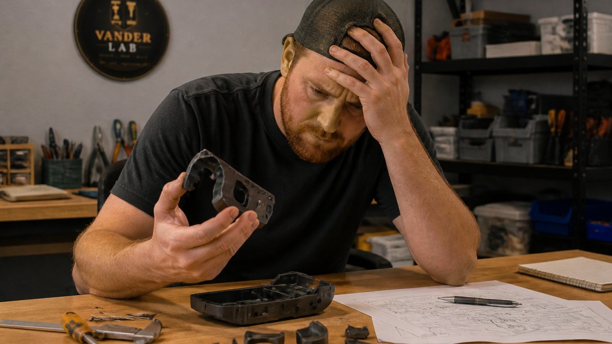
Engineers and makers often encounter this problem. The parts looked perfect on the drawing. The dimensions checked out. Yet when assembly time arrived, pieces wouldn't align. Tolerances stacked in unexpected ways. Materials behaved differently than anticipated.
The good news: most of these failures are preventable. They follow predictable patterns. Once you know what to look for, you can design around them, communicate better with your supplier, and catch problems early.
Tolerance and Dimensional Fit Issues
Tolerance is the allowable variation in a part's dimensions. Think of it as the acceptable range a measurement can fall within.
The real problem emerges when tolerances stack. Imagine assembling five custom parts in sequence. Each one has its own tolerance band. The first part sits within its tolerance.
This is tolerance stack-up, and it's where most custom part fit problems begin.
Many designers specify tolerances that are too loose, assuming wider tolerances mean fewer rejected parts.
The solution requires understanding your assembly's critical dimensions. Some measurements matter more than others. A hole that receives a shaft needs tight control.
Material Selection and Compatibility Problems
Materials don't always behave as their datasheets suggest. A plastic that works fine in a lab test might warp when exposed to heat or humidity during assembly.
Thermal expansion causes real trouble. Aluminum expands at a different rate than steel.
Material compatibility also matters at the chemical level. Some plastics dissolve or degrade when they contact certain adhesives or solvents. Dissimilar metals can corrode when they touch.
Choosing materials requires thinking beyond the individual part. Consider what each material will contact, what temperatures it will experience, and how it will respond to assembly forces.
Manufacturing Quality Control Gaps
Even when design and material selection are sound, manufacturing defects create assembly problems. A CNC machine might drift slightly over the course of a production run. A 3D printer can produce parts with inconsistent wall thickness. Hand-finishing work varies from piece to piece.
Quality control catches some of these issues. Dimensional inspection finds parts that fall outside tolerance. Visual inspection spots surface flaws. But not all defects show up in standard inspection.
The most effective quality control happens at multiple stages: during production, before assembly, and sometimes after assembly begins. Early detection prevents you from building assemblies around defective parts.
Diagnosing Custom Part Fit Problems During Assembly
When assembly fails, the temptation is to blame the parts. Sometimes that's right. Often, the real issue lies in how the design was interpreted, how tolerances were managed, or how the assembly process itself was executed. A structured diagnostic approach separates the real problem from the symptoms.
Step 1: Verify the Design Intent
Start by confirming what the design actually requires. Pull the original CAD files and drawings. Check the revision history. Sometimes parts don't fit because the design changed but one component didn't get updated. A newer version of Part A might have different dimensions, but Part B was still manufactured to the old spec.
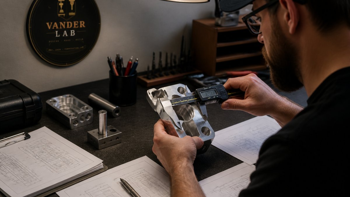
Compare the physical parts against the current drawings. Measure critical dimensions. Document what you find. If parts measure within their specified tolerances but still don't fit, the problem isn't manufacturing quality. It's design or tolerance stack-up.
Ask yourself:
- Are you assembling the latest version of each part?
- Do all parts reference the same revision of the assembly drawing?
- Have any design changes been made since manufacturing started?
- Do the drawings clearly specify how parts should interface?
Step 2: Check Tolerance Stack-Up Across the Assembly
Lay out the assembly sequence on paper. For each step, identify the critical dimension that controls fit. Write down the nominal value and the tolerance band.
Then calculate the worst-case stack. Add up all the upper tolerance limits for dimensions that stack in one direction. Add up all the lower limits for the opposite direction.
If your worst-case stack exceeds your clearance, you've found your problem. The assembly can't work reliably because the parts can vary too much.
The fix usually involves tightening tolerances on the most critical dimensions or redesigning the interface to be less sensitive to variation. Sometimes you can adjust the assembly sequence.
Step 3: Measure and Compare Against Specifications
Measure the actual parts you're trying to assemble. Use precision instruments appropriate to your tolerances. For tight tolerances, calipers aren't enough. You need micrometers or coordinate measuring machines.
Record measurements for every critical dimension. Compare them to the specification. Parts that fall within tolerance but at the extreme edges of the band can still cause assembly problems when combined.
Create a simple spreadsheet. List each part, each critical dimension, the spec range, and the actual measurement. This visual comparison often reveals patterns. Maybe all of Part A is running small. Maybe Part B's hole is consistently oversized.
Custom Part Quality Inspection Before Assembly
Catching problems before assembly prevents wasted time and rework. A smart inspection catches defects that would otherwise cause assembly failures.
Visual and Dimensional Inspection Methods
Start with your eyes. Look for cracks, warping, discoloration, or surface defects. These issues might not show up in dimensional checks but can affect assembly fit or function.
Then measure. For simple parts, calipers work fine. For complex parts or tight tolerances, use micrometers, depth gauges, or coordinate measuring machines. Measure at multiple points. A hole might be perfectly round at one end but slightly tapered at the other.
Document your measurements. Trends matter. If five parts in a row run slightly oversized, something's drifting in the manufacturing process. Catching this early lets you adjust before you produce a whole batch of out-of-spec parts.
Testing Non-Visible Components and Assemblies
Some defects hide inside. A 3D-printed part might have internal voids. A machined part might have stress concentrations. A press-fit assembly might have gaps you can't see.
Testing reveals these hidden problems:
- Pressure testing forces fluid or air through the part to find leaks
- Ultrasonic testing detects internal voids and cracks
- Functional testing runs the part through its actual use case to see if it works
- Dimensional scanning creates a complete 3D map of the part to spot geometry issues
Not every part needs every test. But critical parts, parts with hidden geometry, and parts that will experience stress during use should be tested before assembly.
Assembly Troubleshooting Checklist
When custom parts fail assembly, work through this sequence:
- Confirm all parts are the current revision
- Verify drawings match the actual assembly intent
- Measure critical dimensions on all parts
- Calculate tolerance stack-up for your assembly sequence
- Compare actual measurements to tolerance bands
- Identify which dimensions are causing misfit
- Check for manufacturing defects (cracks, warping, voids)
- Verify material properties match specifications
- Test non-visible components if applicable
- Review the assembly process for errors or missed steps
- Check that you're using the correct assembly tools
- Confirm fasteners and adhesives are appropriate for the materials
- Look for environmental factors (temperature, humidity) affecting fit
- Document findings for the next iteration
Design for Assembly Best Practices
The best way to prevent custom part fit failures is to design assemblies that tolerate variation. This approach, called design for assembly, builds robustness into your product from the start.
Designing Parts That Fit Right the First Time
Think about tolerance from the beginning. Ask which dimensions truly affect fit and function. Tighten tolerances only where necessary.
Use chamfers and tapers on parts that must align. A sharp edge can catch and prevent assembly. A slight taper guides parts into position even if alignment isn't perfect.
Avoid designs that depend on multiple parts fitting perfectly. Instead, use features that accommodate variation. A slot that's slightly oversized lets a shaft slide in even if tolerances stack up.
Consider the assembly sequence. Some sequences are forgiving. Others amplify tolerance stack-up. Design so that early steps aren't sensitive to later variation.
Communication With Your Parts Supplier
Your supplier can't read your mind. If you hand over a drawing with loose tolerances, they'll manufacture to the loosest acceptable dimension.
Be explicit about what matters. Highlight critical dimensions on your drawing. Add notes explaining why certain tolerances are tight. If a dimension affects fit with another part, say so.
Discuss material selection. Your supplier might know that a different material would work better for your application. They might spot design features that are hard to manufacture and suggest alternatives.
Ask about a supplier's manufacturing process. Different machines have different capabilities. What's easy on a modern CNC might be difficult on older equipment.
When Assembly Fails: Root Cause Analysis and Prevention
Assembly failures cost time and money. They also teach you something valuable if you take time to understand what went wrong.
When a failure happens, resist the urge to immediately remanufacture. Instead, investigate. Measure the failed parts. Understand exactly why they didn't fit.
Document your findings. Note which dimensions were problematic. Note whether parts were in tolerance. Note any defects you found.
Then decide on your fix. Sometimes you need tighter tolerances. Sometimes you need a design change. Sometimes you need a different assembly process.
Share what you learned with a supplier. If they manufactured parts that were in tolerance but still caused problems, discuss how to prevent it.
Conclusion
Custom parts fail assembly because of tolerance stack-up, material incompatibility, manufacturing defects, design mismatches, or assembly errors. Finding the real cause requires systematic diagnosis: verify your design, check your tolerances, measure your parts, and test before assembly.
At VanderLab, we work with customers to catch these problems early. Our CAD design and precision fabrication services help you move from rough ideas to parts that fit right. When you're ready to turn your design into precision parts that actually work, get a custom quote and let's build something that fits. You can also browse our precision parts and custom work on our eBay Shop.
Frequently Asked Questions
What are the most common reasons custom parts fail during assembly?
Custom parts fail assembly most often due to tolerance and dimensional fit issues, where parts don't fit together as designed. Material incompatibility, manufacturing defects from quality control gaps, design geometry problems, and assembly errors (using wrong parts, skipping steps, or applying incorrect force) are also frequent causes. Tolerance stack-up across multiple components compounds these issues. Understanding the specific failure point, whether the part itself is wrong, the assembly process has an error, or the design needs revision, determines the fix.
How can incorrect tolerances cause custom parts to fail to fit?
Tolerances define how much variation a dimension can have. When tolerances are too loose, parts may have excessive clearance or won't align properly. When tolerances are too tight, parts won't fit at all due to manufacturing variation. Tolerance stack-up occurs when multiple parts are assembled together, small variations in each part add up, sometimes causing the final assembly to exceed acceptable limits. A part that measures correctly in isolation may still fail to fit if the cumulative tolerance across the assembly wasn't accounted for during design.
How do you troubleshoot a custom part that does not fit?
Start by verifying the design intent: confirm you have the correct part and revision. Next, measure the part against its specifications using precision tools like calipers or micrometers. Compare actual dimensions to the tolerance range on the drawing. If the part measures within spec but still won't fit, check tolerance stack-up by measuring related components. Inspect for manufacturing defects like burrs, warping, or surface damage. Finally, verify assembly technique, wrong orientation, missing steps, or using incorrect tools can prevent proper fit even with good parts.
What measurements should you verify before assembling custom parts?
Verify critical dimensions that affect fit: bore and shaft diameters, hole spacing and locations, surface flatness, and overall length or height. Check that mating surfaces are clean and free of burrs or debris. Confirm the material is correct, different materials can have different thermal expansion or hardness that affects fit. For assemblies with multiple parts, measure the components that will interface with each other. Document all measurements against the original specifications and tolerance ranges. This baseline data helps identify whether fit problems stem from the part itself or the assembly process.