 how-to
How to Prepare CAD Files for CNC Machining
Table of Contents
- What You'll Need Before You Start
- Step 1: Define Your Part Envelope and Critical Dimensions
- Step 2: Handle Hole Features and Thread Specifications
- Step 3: CNC Machining File Format Guide, Choosing and Exporting the Right Format
- Step 4: Suppress Unnecessary Geometry and Validate the File
- Common CNC Machining Design Errors, and How to Avoid Them
- How to Prepare CAD Files for CNC Machining: Assemblies, Version Control, and Surface Finish Notes
- Sending Your CAD Files for CNC Fabrication
- Frequently Asked Questions
Last Updated: September 2, 2026
Knowing how to prepare CAD files for CNC machining is the difference between a part that runs first time and one that requires rework. At VanderLab, we work from customer files every week, and the files that cause delays share the same small, fixable problems. This guide breaks down every step, from setting up your part envelope to choosing the right export format, so your file arrives ready to cut.
The core principle is simple: a CNC machine reads geometry, not intent. If your file has ambiguous tolerances, missing thread callouts, or units set to millimeters when the shop expects inches, the machine will cut exactly what the file says, not what you meant.
What You'll Need Before You Start
Solid file preparation starts before you open the export dialog. You need a CAD environment that supports solid modeling, a clear understanding of the material and process your shop will use, and a checklist mindset that treats every dimension as something a machinist will actually measure.
Before you touch the export settings, confirm: material specified, process confirmed (3-axis milling, turning, routing, or multi-axis), critical dimensions identified, fastener and thread specifications listed, and any post-processing requirements noted. Getting these details sorted before export means the geometry you send actually matches the part you need.
Step 1: Define Your Part Envelope and Critical Dimensions
The part envelope is the bounding box that contains your geometry, the maximum length, width, and height a part occupies before any material is removed. State it in the drawing title block or in a note on the model. Don't make the machinist calculate it from the geometry.
Setting Units and Scale Correctly
Units are the single most common source of catastrophic errors in CNC file preparation. A part modeled in millimeters but exported without embedding unit metadata will be interpreted as inches by many CAM systems, producing a part roughly 25 times larger than intended (nist.gov).
Set your document units before modeling starts. Confirm the units are embedded in the STEP or IGES export. When you open the exported file in a viewer, measure a known feature and verify it reads correctly. This takes 30 seconds and eliminates an entire class of scrap parts.
Managing Tolerances, Fits, and GD&T Annotations
A common mistake is leaving all dimensions at the CAD software's default tolerance, which is usually far tighter than what the process can hold, or far looser than what the assembly requires.
Geometric dimensioning and tolerancing (GD&T) is the standardized system for communicating allowable variation in form, orientation, and location. A GD&T callout on a datum surface tells the machinist exactly how flat that face needs to be.
For functional fits, a shaft going into a bore, a press-fit insert, a sliding dovetail, specify the fit class explicitly. Mark critical dimensions clearly. One practical approach: use a feature control frame or a note that reads "CRITICAL, verify before proceeding" on the two or three dimensions that actually govern function. Everything else can carry standard machining tolerances.
Step 2: Handle Hole Features and Thread Specifications
For every hole in your part, the file needs to communicate: diameter, depth (through or blind), tolerance class, and whether the hole is tapped. A cylindrical cut in a solid model tells the machinist the diameter. It does not tell them the tap drill diameter, the thread form, the thread class, or whether they should stop before the bottom or run through.
Add thread specifications as a note or a model annotation. The format should include thread form, nominal diameter, threads per inch (for unified threads) or pitch (for metric), and class of fit. For example: 1/4-20 UNC-2B THRU tells the machinist everything needed to select the correct tap and verify the finished thread.
For tapped blind holes, specify the full depth of the hole and the minimum thread depth separately. A common error is specifying thread depth equal to hole depth, which leaves no room for the tap's chamfer and results in incomplete threads at the bottom.
Step 3: CNC Machining File Format Guide, Choosing and Exporting the Right Format
Choosing the right file format determines how much geometry survives the transfer and how much manual repair work the shop has to do before cutting starts.
3D Formats: STEP, IGES, and Solid Models
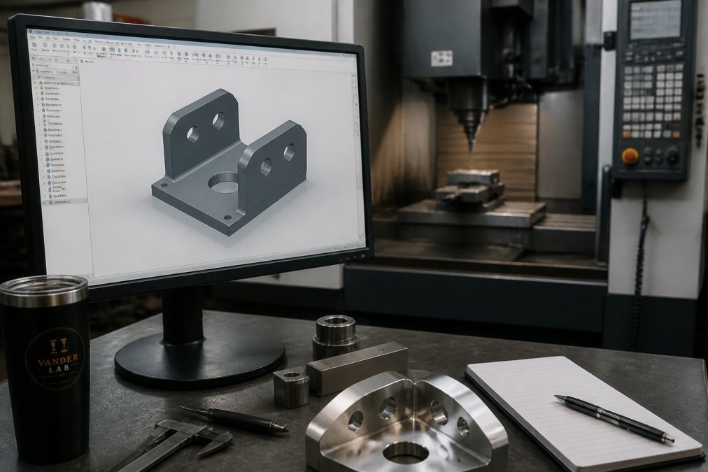
STEP (Standard for the Exchange of Product Data), with the file extension .stp or .step, is the preferred format for 3D CNC file transfer. STEP files carry a watertight solid model with full geometry, unit metadata, and assembly structure. Most CAM platforms import STEP without conversion errors, and the format is vendor-neutral.
IGES (Initial Graphics Exchange Specification), with extension .igs or .iges, is an older neutral format that remains widely supported. IGES transfers surface geometry well but is more prone to open surfaces and missing faces than STEP. Use IGES only when the shop specifically requests it.
Native formats (.sldprt, .prt, .ipt) are readable only by the same software version that created them. Stick with STEP for 3D geometry unless you have a confirmed reason to do otherwise.
When exporting a STEP file, confirm units match your model, geometry type is solid bodies (not surfaces or mesh), and compression is avoided unless the shop requests it.
2D Formats: DXF and DWG for Routing and Profiling
DXF (Drawing Exchange Format) and DWG are 2D vector formats used primarily for flat-profile routing, plasma cutting, waterjet, and laser cutting. If your part is a flat profile cut from sheet stock, a DXF is often all the shop needs.
The most important rule for DXF files: close all contours. An open polyline will cause the toolpath software to fail or produce an incorrect cut path. Before exporting, run your CAD software's geometry validation tool and fix any open loops.
Remove construction geometry, reference lines, and dimension annotations from the DXF before sending. The cutting software reads every entity in the file as potential geometry.
Technical Drawings vs. 3D Models: When You Need Both
Send both when any of the following are true.
| Situation | What to Send |
|---|---|
| Part has tight tolerances on specific features | 3D STEP + 2D drawing with GD&T callouts |
| Part has tapped or threaded holes | 3D STEP + 2D drawing with thread notes |
| Part is a flat profile cut from sheet | DXF only |
| Part requires specific surface finish | 3D STEP + 2D drawing with finish callouts |
| Simple geometry, standard tolerances | 3D STEP only |
| Assembly with multiple mating parts | 3D STEP assembly + 2D assembly drawing |
The 3D model drives the toolpath. The 2D technical drawing communicates the intent, tolerances, threads, surface finish, datum references, and inspection requirements.
Step 4: Suppress Unnecessary Geometry and Validate the File
Before sending any file, the geometry needs to be clean. Feature suppression means hiding or removing model elements that exist for design purposes but have no function in machining: construction planes, sketch geometry, reference bodies, and cosmetic threads.
Geometry validation steps to run before export:
- Check for open surfaces, every solid body should be fully enclosed
- Verify wall thickness, thin walls below the minimum for the material and process will fail
- Confirm no self-intersecting geometry, faces that pass through each other produce invalid toolpaths
- Check for duplicate entities, overlapping faces or coincident edges cause CAM errors
- Review the bounding box, confirm the part envelope matches expectations
Running a validation check takes minutes and can prevent hours of shop floor troubleshooting.
Common CNC Machining Design Errors, and How to Avoid Them
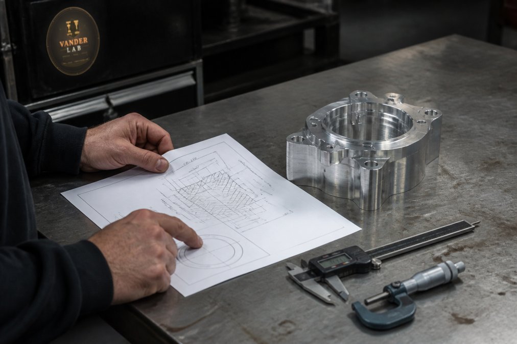
Most CNC machining design errors are not exotic. They're the same handful of problems, repeated across thousands of files, that experienced machinists recognize immediately.
The most frequent issues:
Internal corners with zero radius. CNC end mills are round. They cannot cut a perfectly sharp internal corner. Any internal corner needs a radius at least equal to half the diameter of the smallest tool that will cut it.
Features too deep for the tool. Deep slots and pockets have aspect ratio limits. A slot that's 10 times deeper than it is wide requires a long-reach tool, slow feedrates, and multiple passes.
Undersized text or engraving. Engraved text below a certain stroke width cannot be cut cleanly with available tooling. Text features need to be sized to match the tool diameter being used.
Missing datums. Without defined datum surfaces, the machinist has to infer where to set up the part, introducing variation between setups.
Inconsistent units between model and drawing. The model says millimeters, the drawing title block says inches. This always causes a delay.
Automated DFM Analysis: Catching Problems Before the Machine Does
Automated DFM (Design for Manufacturability) analysis evaluates a CAD model against machining constraints before it reaches the shop floor. DFM tools check for features that are difficult or impossible to machine, undercuts, insufficient draft angles, unsupported thin walls, and features outside the machine's work envelope.
Many CAD platforms now include basic DFM modules. Running a DFM check before sending the file is worth making a standard step in your workflow.
How to Prepare CAD Files for CNC Machining: Assemblies, Version Control, and Surface Finish Notes
Three additional areas matter significantly when the work gets more complex: assemblies, file versioning, and surface finish communication.
Handling Complex Assemblies vs. Single Parts
When sending an assembly for machining, the shop needs to know which parts are being machined, which are purchased hardware, and how the machined parts mate with each other.
Best practice for assembly files: send individual STEP files for each machined part, plus one assembly STEP showing the context. Include an assembly drawing that shows mating dimensions and fit requirements. Identify purchased components separately so the shop knows what to expect.
Version Control and Collaborative Workflows
A machined part is a physical object. Once it's cut, it can't be un-cut. If the shop machines revision A while you've already moved to revision B, you have scrap.
Embed revision information in the file name and the drawing title block. A practical naming convention: PartName_Rev[letter]_[YYYYMMDD].step
For collaborative workflows, establish a single point of truth for released files. The shop should always be able to identify which file is current.
Post-Processing and Surface Finish Requirements
Surface finish requirements belong on the drawing, not in an email. If your part requires a specific finish, for sealing, aesthetics, or wear resistance, that requirement needs to be called out explicitly.
Surface finish is expressed as a roughness value (Ra) in microinches or micrometers. Common callouts: Ra 125 µin (3.2 µm) for standard machined finish, Ra 63 µin (1.6 µm) for smooth finish, and Ra 32 µin (0.8 µm) for fine finish.
Post-processing requirements, anodizing, powder coating, heat treatment, painting, also need to be on the drawing. Some post-processing steps affect final dimensions, and the machinist needs to know whether to machine to nominal or to leave stock for the finishing process.
Sending Your CAD Files for CNC Fabrication
A well-prepared file package includes: a STEP file for each machined part, a PDF of the technical drawing with tolerances and thread callouts, a DXF for any flat-profile features, and a brief cover note listing the material, quantity, and any special requirements.
The cover note is underrated. A single paragraph that says "this is 6061 aluminum, 5 pieces, the M5 holes are tapped, and the mating bore needs to be within ±0.001 inch" saves a phone call and sets the project up correctly from the start.
If you're ready to move from planning to fabrication, VanderLab is here to help. Whether you need feedback on your file before machining begins or want to discuss your project in detail, custom quotes are available to walk through your specific requirements. You can also browse completed work and examples on the VanderLab eBay Shop to see the kind of precision parts and custom pieces we build.
The checklist below covers every preparation step in sequence:
- Units confirmed and embedded in export
- Part envelope documented in drawing title block
- Critical dimensions identified and toleranced
- GD&T annotations on functional features
- All hole features include diameter, depth, and thread specification
- Tap drill diameters and thread depths specified for blind holes
- Unnecessary sketch geometry and construction features suppressed
- Solid model validated, no open surfaces, self-intersections, or duplicate entities
- File exported as STEP with solid body geometry
- DXF contours closed and construction geometry removed
- Surface finish callouts on drawing
- Post-processing requirements noted
- Revision identifier in file name and title block
- Cover note prepared with material, quantity, and special requirements
Getting this right the first time is what keeps a project on schedule and on budget. One project at a time, built right.
Frequently Asked Questions
What file formats are best for CNC machining?
STEP (.stp / .step) is the most universally accepted 3D format for CNC machining because it preserves solid model geometry and metadata across different software platforms. IGES is an older alternative that most shops still accept. For 2D routing and profiling work, DXF and DWG are standard. When submitting CAD files for CNC fabrication, pairing a STEP file with a dimensioned PDF drawing gives the machinist everything needed to cut the part correctly.
What are the most common mistakes when preparing files for CNC?
The most frequent CNC machining design errors include mismatched units (designing in millimeters but exporting in inches), missing or ambiguous tolerances, undersized holes that don't account for tap drill diameter, thin walls that can't survive toolpath forces, and sharp internal corners that no end mill can cut. Sending a file without a technical drawing is another common issue, the drawing communicates intent that a 3D model alone can't always convey, especially for critical dimensions and thread specifications.
Do I need to include technical drawings with my CAD files?
For simple parts with no tight tolerances, a clean STEP file is often enough. For anything with critical dimensions, geometric dimensioning and tolerancing (GD&T) callouts, thread specifications, or specific surface finish requirements, a technical drawing is essential. The drawing tells the machinist what matters most and what the acceptable range of variation is. Submitting both a 3D model and a 2D drawing together reduces back-and-forth and lowers the chance of a part being cut to the wrong spec.
How do tolerances affect CAD file preparation for CNC?
Tolerances define how much a finished dimension can vary from the design intent and still function correctly. Tighter tolerances require slower feeds, more passes, and often more expensive tooling, so calling out tight tolerances only where they matter keeps costs reasonable. In your CAD file, apply GD&T annotations to features like mating surfaces, bearing bores, and datum references. For features where standard machining variation is acceptable, a general tolerance note on the drawing covers everything else without overcomplicating the file.
Preparing CAD files correctly is the foundation of any successful CNC run, and it's where the most preventable delays happen. VanderLab works from customer-supplied files and from scratch, with CNC routing, 3D printing, and CAD design capabilities built into the same home fabrication lab in Mebane. Whether you're starting from a sketch or a finished STEP file, reach out through the VanderLab custom quote form to talk through what your project needs and get it made right.
This article was written using GrandRanker