 how-to
How to Avoid Layer Lines in 3D Printing (2026 Guide)
Table of Contents
- Why Layer Lines Appear in 3D Printing
- 3D Print Layer Height Settings That Reduce Visible Lines
- Advanced Slicer Settings Beyond Layer Height
- Mechanical Calibration: Belts, Lead Screws, and Gantry Alignment
- Choosing Filament to Minimize Layer Lines in 3D Printing
- Post-Processing 3D Prints for a Smooth Surface Finish
- Common Mistakes to Avoid
- Frequently Asked Questions
Last Updated: August 31, 2026
Layer lines are the most common complaint in 3D printing, and they're also the most fixable. The VanderLab team works with 3D printed parts daily, from functional prototypes to custom keepsakes, and we've learned that avoiding layer lines comes down to three things: slicer configuration, mechanical calibration, and post-processing. Get all three right and your prints look genuinely finished.
Below, we'll walk through each factor in sequence, from the settings you adjust before you hit print, to the sandpaper and primer that close the gap afterward.
Why Layer Lines Appear in 3D Printing
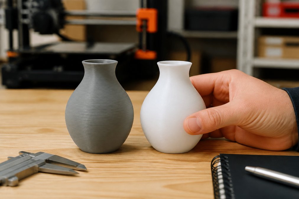
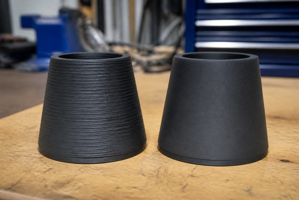
Layer lines appear because FDM printers build objects by depositing material one horizontal layer at a time. Each layer has measurable thickness, and the boundaries between layers show as ridges or bands. Thicker layers mean more pronounced ridges.
But visible layer lines aren't just about layer height. They're also caused by inconsistent extrusion, mechanical vibration, poor filament quality, and misaligned components. A print with 0.1 mm layer height can still look rough if the extruder is skipping or belts are loose. Understanding the root cause tells you where to fix the problem, chasing smooth surfaces by only reducing layer height is a common mistake that slows print times without addressing underlying issues.
3D Print Layer Height Settings That Reduce Visible Lines
3D print layer height settings are the first and most direct way to reduce visible layer lines. Layer height should be between 25% and 75% of your nozzle diameter (peer-reviewed research). With a standard 0.4 mm nozzle, that's 0.1 mm to 0.3 mm. The sweet spot for most prints is 0.2 mm, which balances surface quality with reasonable print times.
Choosing the Right Layer Height for Your Nozzle Diameter
Printing at a layer height exceeding 75% of your nozzle diameter causes poor layer adhesion and irregular extrusion. Going below 25% creates over-compression, where the nozzle drags against already-deposited material.
For a 0.4 mm nozzle:
- 0.1 mm: Fine detail, slow prints, best for display models
- 0.2 mm: All-purpose, good surface quality, reasonable speed
- 0.3 mm: Faster prints, more visible lines, better for structural parts
Switching to a 0.2 mm nozzle lets you print at 0.05-0.1 mm layer heights for very fine surfaces, but print times increase dramatically. For most functional parts, a 0.4 mm nozzle at 0.15-0.2 mm layer height hits the best balance.
Using Adaptive Layers and Variable Extrusion Width
Adaptive layers automatically adjusts layer height based on model geometry. On curved surfaces, it reduces layer height to preserve detail. On flat walls, it uses taller layers to save time. Variable extrusion width widens or narrows the extrusion path to fill areas more precisely, reducing gaps and improving surface consistency. Both features are available in most modern slicers.
Advanced Slicer Settings Beyond Layer Height
Print Speed, Flow Rate, and Perimeter Count
Print speed directly affects surface finish. Printing outer perimeters too fast causes the extruded bead to not fully settle before the nozzle moves on. Try outer walls at 25-30 mm/s if your infill runs at 60 mm/s.
Flow rate calibration is equally important. Under-extrusion leaves gaps; over-extrusion creates blobs. Calibrate by printing a single-wall cube and measuring thickness with calipers. Adjust flow rate until measured thickness matches your extrusion width setting.
More perimeters mean a denser, more uniform outer shell. For display-quality prints, three or four perimeters produce noticeably smoother results than the default two.
| Setting | Recommended Value | Effect on Surface |
|---|---|---|
| Outer wall speed | 25-30 mm/s | Smoother bead deposition |
| Flow rate | Calibrated to ±1% | Eliminates gaps and blobs |
| Perimeter count | 3-4 | Denser, more uniform shell |
| Layer height | 25-50% of nozzle diameter | Finer surface detail |
Seam Alignment, Retraction Settings, and Bridging
Every closed perimeter has a seam where the nozzle starts and stops. Most slicers offer seam alignment options: "back" places the seam on the rear, "sharpest corner" hides it in a geometric feature, and "random" distributes it across the surface.
Retraction settings control how much filament the extruder pulls back during nozzle travel. Too little causes stringing and blobs; too much causes gaps at the next extrusion. Retraction distance and speed need tuning per filament type and extruder design.
Increasing fan speed during bridges and reducing bridge flow rate to around 90% helps most materials span cleanly without sagging.
Mechanical Calibration: Belts, Lead Screws, and Gantry Alignment
Slicer settings can only compensate so much for mechanical imprecision. If your hardware isn't dialed in, surface artifacts will persist regardless of slicer configuration.
Belt Tension and Z-Axis Wobble
Loose belts cause the toolhead to oscillate slightly during direction changes, creating a ripple pattern on vertical surfaces called "ringing" or "ghosting." Check belt tension by plucking each belt like a guitar string. A properly tensioned belt produces a consistent, mid-range tone. Tighten gradually and recheck.
Z-axis wobble comes from a bent or misaligned lead screw, creating a repeating wave pattern with pitch matching the lead screw's thread pitch. Correct it by checking lead screw straightness, ensuring the coupler between motor and lead screw isn't binding, and verifying that Z-axis linear rails or rods are parallel.
E-Steps Calibration and Under-Extrusion Fixes
E-steps calibration defines how many stepper motor steps correspond to 1 mm of filament movement. Incorrect E-steps cause systematic under-extrusion or over-extrusion across every print. This should be rechecked when switching extruder designs or filament diameter.
To calibrate, mark 100 mm of filament above the extruder, command the printer to extrude 100 mm, and measure how much was actually moved. Calculate the correction factor and update the firmware value.
Under-extrusion from other sources includes partial nozzle clogs, worn drive gears, a cold end that's too cold for the filament, and excessive retraction. The RepRap community wiki on under-extrusion troubleshooting covers each systematically.
Choosing Filament to Minimize Layer Lines in 3D Printing
Filament quality has direct impact on layer lines. Inconsistent filament diameter causes flow variation that shows up as surface banding even when all other settings are correct. Quality filament maintains diameter tolerance within ±0.02 mm across the spool.
Material choice also matters:
- PLA is easiest to print and sands well. It's the best starting point for surface-quality experiments.
- PETG has a slightly glossier surface but is more prone to stringing and doesn't sand as cleanly.
- ABS prints with more visible layer lines but responds exceptionally well to acetone vapor smoothing.
- ASA behaves similarly to ABS with better UV resistance and accepts acetone smoothing.
- TPU is flexible and difficult to sand. Surface finish depends largely on print settings rather than post-processing.
Filament storage matters too. Moisture-absorbed filament produces bubbles and inconsistency during extrusion. Keeping filament in sealed containers with desiccant prevents a class of surface defects that no slicer setting can fix.
Post-Processing 3D Prints for a Smooth Surface Finish
Post-processing closes the gap between "good print" and "finished part." Even a well-calibrated printer with optimized settings will leave some layer lines visible.
Sanding with Progressive Grit Sandpaper
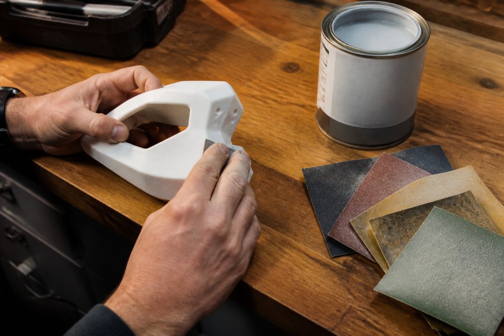
Sanding is the most universally applicable post-processing method. The key is using progressive grit sandpaper, starting coarse and finishing fine. Skipping grits leaves scratches that finer grits struggle to remove. A typical sequence:
- 80-120 grit to remove the most prominent layer lines
- 220 grit to smooth the surface left by coarser paper
- 400 grit to refine further
- 800-1000 grit for a pre-paint surface
- 1500-2000 grit (wet sanding) for a near-polished result
Wet sanding with water or light lubricant at finer grits reduces heat buildup, which matters for PLA since it softens at relatively low temperatures. Sand in circular or cross-hatched motions rather than following layer lines.
Primer Filler, Acetone Vapor Smoothing, and Material-Specific Methods
Filler primer is spray-applied primer with higher solids content than standard primer. It fills small surface imperfections and creates a uniform base for paint. Two to three light coats, sanded between each, produce a surface that looks injection-molded when painted.
Acetone vapor smoothing works specifically on ABS and ASA. Acetone dissolves the outer layer, causing it to reflow into a smooth surface without sanding. Place the print above a small amount of acetone in a sealed container and allow vapors to work for several minutes to hours. As noted in guidance on safe solvent handling from the Occupational Safety and Health Administration, acetone should be used in a well-ventilated area away from ignition sources.
Epoxy coating works on any filament type. Brush-applied epoxy fills layer lines, self-levels, and cures hard. XTC-3D and similar brush-on coatings are purpose-made for 3D prints and produce excellent results on PLA without acetone's safety considerations.
Common Mistakes to Avoid
Most failed attempts to eliminate layer lines come down to repeating errors.
Chasing layer height alone. Dropping to 0.1 mm without addressing mechanical issues or flow rate just means slower prints with the same artifacts. Fix the root cause first.
Skipping flow rate calibration. Under-extruding at any layer height produces rough, gapped surfaces. Calibrate flow rate before optimizing anything else.
Ignoring filament condition. Wet filament produces inconsistent extrusion that no slicer setting corrects. If prints suddenly look worse despite unchanged settings, check filament moisture.
Sanding too aggressively. Starting with 80 grit and stopping there leaves deep scratches. Progressive grit sequences exist for a reason.
Using acetone on PLA. Acetone does not smooth PLA. Use appropriate solvents or coatings for your material.
Printing orientation. Layer lines are always horizontal relative to the print bed. Reorienting a model so critical surfaces are printed vertically or at an angle reduces visible lines without changing settings.
Getting smooth 3D prints takes patience, and the path from rough to finished usually runs through all three areas covered here: slicer configuration, mechanical calibration, and post-processing. At VanderLab, we work through this process on every custom part we produce, from functional prototypes to personalized keepsakes. If you'd rather hand the whole thing off, our team handles design, printing, and finishing to bring your idea to life exactly as you pictured it. Reach out and let's build something together.
Frequently Asked Questions
Is it possible to 3D print without layer lines?
Completely eliminating layer lines through printing alone is not realistic with FDM technology, since the process builds parts layer by layer. However, combining a very low layer height (0.1 mm or below), optimized slicer settings, and post-processing steps like sanding and primer filler can reduce layer lines to the point where they are nearly invisible to the naked eye. For truly smooth surfaces, post-processing 3D prints is the most reliable path.
Does layer height affect 3D print surface quality?
Yes, layer height is one of the biggest factors in surface quality. A lower layer height means thinner layers, which produces a smoother surface with finer detail. Most printers perform well between 0.1 mm and 0.2 mm for quality prints. Going below 25% of your nozzle diameter can cause adhesion problems, so match your layer height to your nozzle size. Adaptive layers in your slicer can automatically reduce height on curved or angled surfaces where lines are most noticeable.
How do I remove layer lines from PLA?
Sanding is the most accessible method for PLA. Start with 220-grit sandpaper to knock down the ridges, then work up through 400, 800, and 1000 grit for a progressively smoother surface. Apply a filler primer spray between sanding stages to fill remaining gaps. Unlike ABS, PLA does not respond to acetone vapor smoothing, so mechanical sanding and primer are your primary tools. For intricate geometry, spot-apply filler primer and sand carefully by hand.
What slicer settings help reduce layer lines beyond layer height?
Several slicer settings work together to reduce surface artifacts. Increasing perimeter count adds more outer walls, which hides internal layer transitions. Slowing print speed on outer perimeters improves extrusion consistency. Dialing in flow rate to match your filament's actual diameter prevents over- or under-extrusion. Seam alignment settings let you hide the layer start point in a less visible spot. Retraction settings reduce blobs and stringing that make layer lines stand out even more.
This article was written using GrandRanker