 how-to
How to Design Parts for Tight Tolerances: A 2026 Guide
Table of Contents
- What a Tight Tolerance Actually Means on a Drawing
- Geometric Dimensioning and Tolerancing Basics Every Designer Needs
- How to Reduce Tolerance Stack-Up Before You Send CAD Files
- Step-by-Step: Designing a Part for Tight Tolerances
- Measuring Tools for Precision Parts: What to Check and When
- Cost-Effective Tolerance Design: Where to Loosen and Where to Hold
- Common Mistakes to Avoid on Tight Tolerance Projects
- Frequently Asked Questions
Last Updated: September 10, 2026
What a Tight Tolerance Actually Means on a Drawing
A tight tolerance is a narrow allowable range between a part's intended dimension and its finished dimension, and designing for tight tolerances means deciding, feature by feature, which numbers genuinely need that narrow band. A part calling for ±0.001 in on every surface isn't precise; it's expensive and often impossible to hold.
Reading Tolerance Numbers in Inches and Millimeters
A callout like 1.000 ±0.005 in means the finished dimension must land between 0.995 and 1.005 in; in metric, that same feature might read 25.00 ±0.13 mm. Machinists read the total band, not the plus-or-minus figure, because the band is what the process has to hold. A ±0.005 in callout is a 0.010 in window; ±0.0005 in is a 0.001 in window, different equipment and setup time.
How Material Properties Change What You Can Hold
Material properties decide how much of your tolerance budget survives the cut. Aluminum moves with heat and cuts cleanly; stainless steel work-hardens; plastics like ABS and PLA creep and absorb moisture. A hole that measures perfectly on the bench can drift out of spec after the part cools.
Geometric Dimensioning and Tolerancing Basics Every Designer Needs
Geometric dimensioning and tolerancing basics cover the symbols and rules that control form, orientation, location, and runout. They exist because a plus-or-minus number alone can't describe a hole's position or a face's flatness, letting you say exactly what matters instead of over-constraining everything.
The Four Primary Types of Geometric Tolerances
- Form: flatness, straightness, circularity, cylindricity. Controls the shape of a single feature.
- Orientation: parallelism, perpendicularity, angularity. Controls how one feature sits relative to a datum.
- Location: position, concentricity, symmetry. Controls where a feature sits relative to datums.
- Runout: circular and total runout. Controls how much a rotating surface wobbles.
How to Reduce Tolerance Stack-Up Before You Send CAD Files
Tolerance stack-up is the accumulation of individual feature tolerances across an assembly, and reducing it starts with identifying which dimensions combine to affect fit. If three stacked features each carry ±0.005 in, the worst-case stack is ±0.015 in, fine for a decorative enclosure, fatal for a mating joint. Two moves help most projects: dimension from a single common datum instead of chaining, and loosen any feature that doesn't feed the critical fit.
ASME Y14.5 dimensioning and tolerancing standard
Step-by-Step: Designing a Part for Tight Tolerances
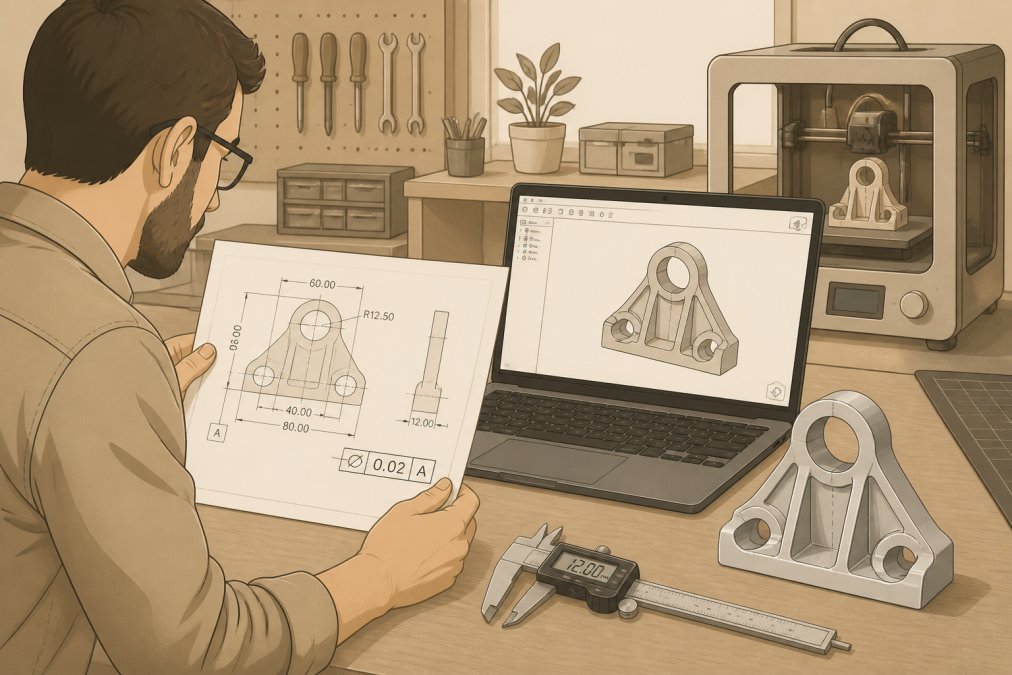
Designing for tight tolerances is a sequence, not a single decision. Work through these five steps in order and you'll catch most problems while they're still cheap to fix.
Step 1: Define the Function Before the Feature
Write down what the part must do before you dimension anything. A bracket holding a cover rarely needs a precision bore; a shaft that rides in a bearing does. Function tells you which features earn a tight number and which can stay loose.
Step 2: Pick the Process That Can Hold the Number
Match the process to the tolerance before you finalize the drawing. A hobby-grade 3D printer and a CNC router hold very different windows. If unsure, ask the shop what they can reliably hit, then design to that.
Step 3: Set Datums, Then Dimension From Them
Choose datums that reflect how the part mounts and functions, then dimension from them. This is the biggest lever for reducing stack-up and giving an inspector a repeatable reference.
Step 4: Budget Tolerances Per Feature, Not Per Part
Assign each feature its own allowance based on what it does. A blanket tolerance note forces every surface to the tightest requirement, driving cost with no functional benefit.
Step 5: Review the Drawing Like a Machinist
Read your drawing the way the person cutting it will. Can I hold this setup? Is this dimension reachable with a standard tool? If a feature is hard to reach or measure, it's hard to hold, and the tolerance should reflect that.
Measuring Tools for Precision Parts: What to Check and When
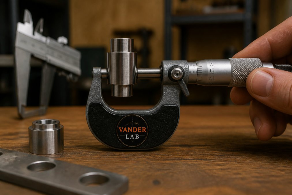
Measuring tools for precision parts range from calipers for general dimensions to micrometers, height gauges, and coordinate measuring machines for tighter work, and the tool must be at least four times more precise than the tolerance it's checking. A caliper reading a ±0.001 in feature isn't a valid inspection; it's a guess. Match the instrument to the band, and verify the tool before trusting the number.
The 4:1 Rule and Why It Sets Your Tooling Floor
The 4:1 rule (sometimes 10:1 for critical work) says your instrument's resolution and accuracy should be at least four times finer than the tolerance you're verifying. A ±0.005 in feature needs a tool good to about ±0.00125 in; a ±0.0005 in feature needs about ±0.000125 in, CMM or surface-plate territory, not caliper territory. Skip this rule and you'll pass out-of-spec parts or reject good ones.
Matching the Instrument to the Feature
| Tolerance Band | Suitable Measuring Tool | Typical Use |
|---|---|---|
| ±0.010 in and looser | Calipers, steel rule | General fit checks |
| ±0.005 in | Micrometer, height gauge | Mating features |
| ±0.001 in | Micrometer, bore gauge, CMM | Bearing fits, precision bores |
| ±0.0005 in and tighter | CMM, surface plate setup | Critical aerospace and tooling work |
A few feature-specific notes that the table can't capture:
- Holes and bores: use a bore gauge or pin gauge, not the inside jaws of a caliper. Caliper inside jaws are notoriously inconsistent on small diameters.
- Flatness and parallelism: a surface plate, dial indicator, and height gauge will get you there for most shop-floor checks; a CMM is the reliable answer once you're under ±0.001 in.
- Threads and profiles: thread wires, thread micrometers, or an optical comparator. A caliper across a thread crest tells you almost nothing useful.
- Soft materials: plastics like ABS and PLA deform under a micrometer's anvil pressure. Use a light-touch or non-contact method, or accept that your reading is approximate.
Calibration, Temperature, and the Shop Environment
Every measuring tool drifts. Micrometers and calipers should be checked against a known standard, a gauge block or calibrated setting rod, before a critical inspection run, and sent out for calibration on a regular schedule. A tool reading 0.0005 in off will quietly pass bad parts all day.
Temperature matters more than most beginners expect. Steel grows roughly 6 microinches per inch per degree Fahrenheit, so a 6 in aluminum part measured in a 60°F shop versus a 90°F shop can differ by more than a thousandth of an inch before any machining error enters the picture. For work at ±0.001 in or tighter, let the part and tool reach thermal equilibrium in the same room, roughly one hour per inch of thickness for steel, longer for plastics.
Gage R&R: When the Measurement Is the Problem
If two people measure the same feature and get different numbers, the gage system, not the part, may be the issue. A gage repeatability and reproducibility (R&R) study separates variation caused by the tool (repeatability) from variation caused by the operator (reproducibility). Most practitioners aim for combined gage variation under 10% of the tolerance band for critical features and under 30% for anything you'll ship. If gage R&R eats more than a third of the tolerance, tighten the measurement method before the part.
What to Measure, and When
Not every feature needs a full inspection. A practical plan covers three tiers:
- First-article inspection (FAI): measure every dimension on the drawing for the first part of a run, catching setup errors, wrong tool offsets, and drawing misreads before they repeat.
- In-process checks: measure features most likely to drift, bores that wear the cutter, thin walls that deflect, anything affected by heat, at intervals, not just at the end.
- Final inspection: verify critical-to-function dimensions and any feature the customer will check on receipt. Everything else can be sampled.
A Note for Small-Batch and One-Off Work
A full CMM setup doesn't make sense for a single bracket or replacement knob. For low-volume work, a calibrated micrometer, granite surface plate, gauge blocks, and dial indicator cover the vast majority of tight-tolerance features. The 4:1 rule still applies, just with hand tools instead of a coordinate machine. What matters is that the tool you reach for is genuinely capable of the number on the drawing.
Cost-Effective Tolerance Design: Where to Loosen and Where to Hold
Cost-effective tolerance design means spending your precision budget only where it changes how the part works. Hold the numbers that affect fit, function, or safety. Loosen everything else.
Why Tighter-Than-Necessary Tolerances Raise Production Costs
Every step tighter adds inspection time, slower feeds, more setup, and more scrap. A feature needing ±0.010 in can often be produced in a single pass; the same feature at ±0.001 in may require multiple passes, a temperature-controlled shop, and a CMM check on every part. The cost curve isn't linear, and the designer's drawing sets it.
Common Mistakes to Avoid on Tight Tolerance Projects
The most common tight-tolerance mistakes are blanket tolerance notes, missing datums, sharp internal corners no cutter can reach, and tolerances on features that can't be measured. Each pushes cost up and reliability down, and a short review before you send CAD files catches nearly all of them.
The Mistakes, and What They Actually Cost You
- Blanket tolerance notes. A title-block note like "ALL DIMENSIONS ±0.001 in" forces every surface, including ones nobody will measure, into the tightest band. The fix is a general tolerance note (often ±0.010 in or ±0.005 in) plus specific callouts only where needed.
- Missing or inconsistent datums. A position tolerance without a datum reference frame is unmeasurable. Worse, datums that don't match how the part mounts will pass inspection and fail in the assembly.
- Sharp internal corners. Every end mill has a corner radius. A square internal corner forces the machinist to violate the print or burn extra time with a smaller tool and a corner-picking pass. Call out the largest radius the function allows.
- Tolerances on unmeasurable features. If a feature can't be reached with a probe, gauge, or CMM stylus, it can't be verified, an unverifiable tolerance is a rejection waiting to happen.
- Ignoring material behavior. Thin walls deflect under cutting force, plastics creep after machining, and heat-treated parts move during the quench. A tolerance fine on paper can be impossible on the actual material.
- Designing for the drawing instead of the process. A ±0.0005 in bore on a 3D-printed part is a mismatch. Pick the process first, then set the numbers it can actually hold.
The Hidden Steps: Post-Processing and Assembly
This is the part most tight-tolerance guides skip. A part that comes off the machine in spec can still fail after finishing:
- Anodizing and plating add thickness, typically 0.0002 in to 0.001 in per surface for common anodize types. A bore on-size before anodize can be undersize after. Design the pre-finish dimension accordingly, or mask the feature.
- Heat treatment moves parts. Quenching and tempering can shift dimensions by several thousandths on a part machined to ±0.001 in. Machine after heat treat, or leave stock and finish to size afterward.
- Bead blasting, tumbling, and polishing remove material and round edges. A sharp corner called out at ±0.002 in won't survive a tumble.
- Assembly stack-up is where individual in-spec parts can still produce an out-of-spec assembly. If three parts each sit at the edge of their tolerance in the same direction, the assembly is out of spec even though every part passed.
The practical move is to note post-processing on the drawing and budget tolerance for it, rather than treating finishing as an afterthought.
Small-Batch and One-Off Reality
Most tight-tolerance advice online is written for production runs of thousands. If you're building a single replacement part, the rules shift:
- Setup cost dominates. On a one-off, the machinist's setup time is often the largest line item. Designing features reachable in one setup, same side, same tool, same orientation, saves more than shaving a thousandth off a tolerance.
- Standard stock sizes matter. Designing around bar stock, plate thicknesses, and common fastener sizes avoids custom material orders that only make sense at volume.
- Loosen what you can, hold what you must. On a single part, every tight callout is a chance for a rework cycle. Save tight numbers for the one or two features that actually control fit.
- Ask the shop what they can hold. A home fabrication shop with a benchtop CNC router and hobby 3D printer has a different capability envelope than a production machine shop. Designing to actual capability, not a generic spec sheet, is what gets a one-off part right the first time.
If you'd rather not source tooling and stock yourself, VanderLab keeps a rotating selection of fabrication gear and shop items in its eBay Shop, and for one-off or small-batch work you can always reach out for Custom Quotes before finalizing your drawing.
Pre-Send Checklist
- Every tight tolerance traces to a functional requirement
- Datums are defined and match how the part mounts
- Internal corners have a realistic tool radius
- Each tolerance can be measured with an available instrument
- The chosen process can actually hold the tightest callout
- Post-processing (anodize, heat treat, finish) is noted and tolerance-budgeted
- Assembly stack-up has been checked, not just individual features
- The design fits the actual capability of the shop making it
NIST engineering metrology resources
Frequently Asked Questions
Is 0.05 mm a tight tolerance?
In most machine shops, 0.05 mm (about 0.002 in) counts as tight for metal parts. Standard CNC machining typically holds around plus or minus 0.13 mm, so 0.05 mm requires sharp tooling, stable fixturing, and temperature control in the shop. Whether it is necessary depends on function. If that 0.05 mm sits on a bearing bore or a sealing surface, it is worth the extra cost. If it sits on a clearance hole, loosening it to 0.13 mm saves money without hurting the assembly.
How do I reduce tolerance stack-up in a multi-part assembly?
Start by identifying the dimension chain that controls function, then shorten it. Fewer parts in the chain means less variation to add up. Where you cannot remove parts, move the tight tolerance to a single controlling feature and let the other dimensions run loose. Designing a slip fit instead of a press fit also absorbs stack-up without extra machining. Finally, run the math both ways, worst case and statistical, so you know how much variation the assembly can actually absorb before parts stop fitting.
Which measuring tools do I need to verify precision parts?
Match the tool to the tolerance, not the other way around. Calipers are fine for plus or minus 0.1 mm checks but not for 0.02 mm work. Micrometers and bore gauges handle most round features. Pin gauges verify hole sizes fast on a production run. For GD&T callouts like flatness or position, a height gauge on a surface plate or a coordinate measuring machine gives you real numbers. A good rule: the measuring tool should resolve to about one-tenth of the tolerance you are checking.
Why does designing for tighter-than-necessary tolerances increase production costs?
Every step tighter usually means slower cutting, more frequent tool changes, extra inspection, and a higher scrap rate. A feature held at plus or minus 0.025 mm can take several times longer to machine than the same feature at plus or minus 0.13 mm, and more parts fail inspection along the way. The fix is to tolerance by function. Put tight numbers only on surfaces that mate, seal, or locate, and leave cosmetic or clearance features loose. That single habit cuts cost more than any other design change.