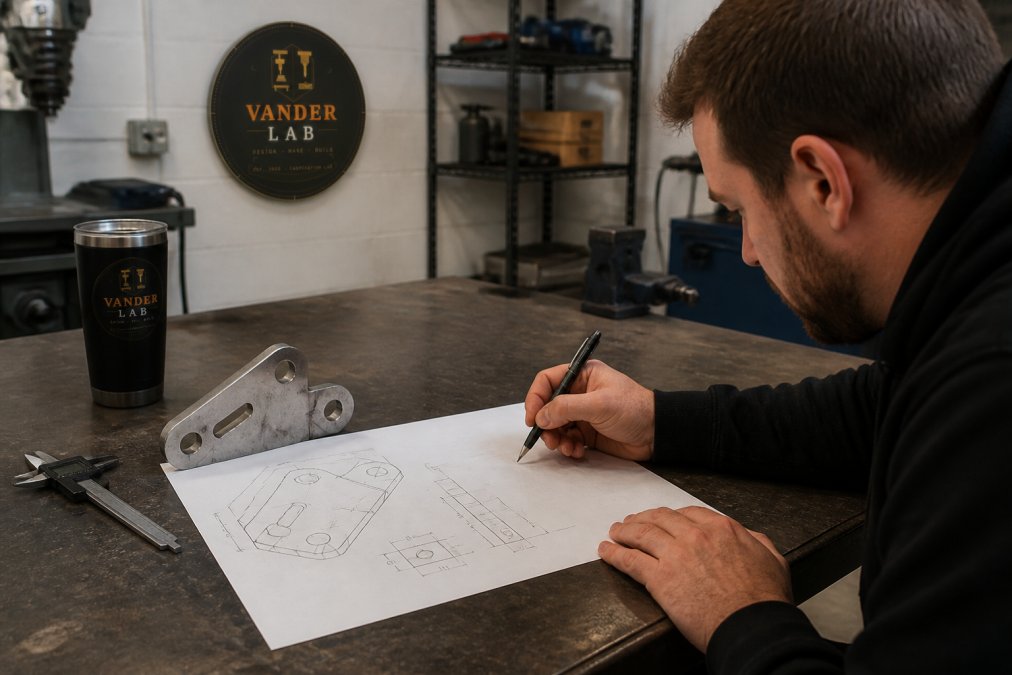
 how-to
How to Convert Sketches to CAD Files: A 2026 Guide
Table of Contents
- What You'll Need Before You Convert a Sketch to CAD
- Step 1: Prepare Your Hand-Drawn Sketch for Conversion
- Step 2: Trace Your Sketch in CAD Software
- Step 3: Try Automated and AI-Powered Conversion Tools
- The Best Software for Sketch to CAD Conversion
- CAD File Conversion Best Practices
- Common Mistakes to Avoid When Converting Sketches
- When to Hand It Off to a Fabrication Shop
- Frequently Asked Questions
Last Updated: September 23, 2026
What You'll Need Before You Convert a Sketch to CAD
Turning a napkin sketch into a clean CAD file starts with one honest question: how good is your source image? A sharp, well-lit scan saves hours of tracing. A blurry phone photo costs them back.
Scanning Hardware and Image Quality Basics
Any modern scanner or phone camera can capture a sketch. What matters is resolution and contrast.
- Scan at 300 to 600 DPI. Below 300, thin pencil lines break up and tracing gets messy.
- Use flat, even lighting. Shadows across the page create false edges.
- Shoot straight down. Angled photos distort proportions before you even start.
- Keep the original clean. Smudges and stray marks become geometry you'll delete later.
Step 1: Prepare Your Hand-Drawn Sketch for Conversion
Cleanup before conversion beats cleanup after. A few minutes here removes hours of editing later.
- 2D part or profile: you'll want a DXF or SVG.
- Floor plan or layout: DWG works best.
- 3D object: you'll need a 2D base sketch before extruding.
Step 2: Trace Your Sketch in CAD Software
Tracing is the most reliable path from sketch to CAD, especially for parts that need tight tolerances. You import the image, scale it, then draw over it with real geometry.
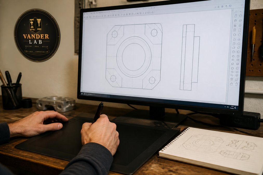
Here's the workflow in most CAD programs:
- Import the cleaned image as a reference underlay.
- Set the scale using one known dimension.
- Draw lines, arcs, and polylines over the sketch.
- Use splines only where curves are truly freeform.
- Lock your layers so the reference image stays put.
Setting Scale and Dimensions
Scale is where most first attempts go wrong. An unscaled sketch is just a picture.
- Always dimension critical features before you trust the drawing.
- Check your units early. Mixing inches and millimeters ruins a file fast.
- Re-verify after edits. Small scale drift creeps in during cleanup.
Step 3: Try Automated and AI-Powered Conversion Tools
Automated tools can turn a scanned sketch into vector geometry in seconds. They work best on clean, high-contrast line art, and they struggle with messy freehand drawings.
- Centerline tracing follows the middle of a stroke and returns a single clean path. This is what you want for a pencil profile, a bracket outline, or anything headed to a CNC router.
- Outline tracing follows both edges of a stroke and returns a closed shape. Great for logos and signage, wrong for a part that needs one cut line.
- Shape recognition tries to identify circles, arcs, and straight segments and rebuild them as true geometry. When it guesses right, the result is cleaner than anything you'd trace by hand. When it guesses wrong, you get a circle where you drew an oval.
- AI sketch-to-model tools attempt to go past 2D and propose a 3D form. Useful for concept work, unreliable for anything with a tolerance callout.
What to Check the Moment the Conversion Finishes
Before you do anything else with the file, run this quick pass. It catches the errors that are cheapest to fix right now and most expensive to find after machining.
- Count the entities. If a simple rectangle came back as 40 separate lines, the trace mode was wrong. Redo it rather than cleaning it.
- Zoom to the corners. Auto-trace almost always leaves tiny gaps where lines should meet. Close them now.
- Check for duplicate geometry. Two lines stacked on top of each other look fine on screen and wreck a toolpath.
- Measure one known feature. Confirm the conversion didn't quietly rescale the drawing.
- Look for text. OCR on hand lettering is unreliable. Retype any dimensions or labels as real text rather than trusting traced outlines of letters.
Post-Conversion Cleanup and Optimization
Most guides stop at the conversion. This is the part they skip, and it's where the real time goes.
- Join and weld. Merge collinear segments into single lines and stitch touching endpoints into continuous polylines. A profile that should be one closed loop needs to be exactly that.
- Close every loop. CAM software cannot cut an open profile. Use an overkill or delete-duplicates command, then a close-gaps tolerance, then verify by hatching the region. If it hatches, it's closed.
- Remove zero-length and micro segments. Slivers shorter than your smallest tool diameter will never cut cleanly and often crash a toolpath.
- Smooth splines into arcs where you can. A true arc is easier for a machine to follow than a spline with dozens of control points, and it produces a better finish.
- Re-apply your scale. Cleanup operations can nudge geometry. Re-measure your anchor dimension after every major edit.
- Purge and audit. Run your CAD program's audit or purge command to strip unused layers, blocks, and styles before export. A bloated file is a file that fails to open on someone else's machine.
Matching the Tool to the Job
There's no single best converter. There's a best converter for what you're converting.
- Flat signage, logos, and vinyl-ready art: a vector graphics editor with a trace function is usually the fastest path, and the output is already in a format cutters like.
- Mechanical parts with tolerances: trace manually in a parametric CAD program. You keep control of every dimension, and the model stays editable.
- High-volume simple line art: an AI conversion app earns its keep when you're processing many similar sketches and can accept a cleanup pass on each.
- Anything headed to 3D printing: convert to a clean 2D profile first, then extrude or revolve. Skipping the 2D step is how you end up with a model full of self-intersecting faces.
The Best Software for Sketch to CAD Conversion
The best software for sketch to CAD conversion depends on your output. For precise 2D parts, a parametric CAD program with good tracing tools wins. For quick vector art, a dedicated raster-to-vector tool is faster.
A few categories cover most needs:
| Tool Type | Best For | Typical Output |
|---|---|---|
| Parametric CAD | Precision parts, mechanical design | DXF, DWG, STEP |
| Vector graphics software | Logos, signage, flat art | SVG, PDF, DXF |
| AI conversion apps | Quick drafts from clean sketches | SVG, DXF |
| 3D modeling software | Parts needing extrusion or 3D print | STL, STEP, OBJ |
CAD File Conversion Best Practices
Good files share the same habits. Follow these and your drawing will survive the trip to a machine.
- Use layers. Keep geometry, dimensions, and reference images separate.
- Close your shapes. Open polylines break CAM toolpaths.
- Snap to grid and endpoints. Floating lines cause gaps.
- Name your layers clearly. Future-you will thank present-you.
- Save native files first. Export DXF or SVG only when the drawing is final.
Understanding File Formats: DXF, DWG, SVG, and PDF
Each format has a job. DXF is the universal exchange format for CAD and CNC work. DWG is the native format for many CAD programs and handles complex drawings well. SVG is vector art for the web, laser cutters, and vinyl cutters. PDF is for sharing and printing, not editing.
Common Mistakes to Avoid When Converting Sketches
Most failed conversions trace back to a handful of avoidable errors.
- Skipping scale. An unscaled sketch produces a part that doesn't fit.
- Tracing on a blurry scan. You end up redrawing noise.
- Leaving duplicate lines. Overlapping geometry confuses CAM software.
- Ignoring units. A millimeter file read as inches is off by a factor of 25.
- Forgetting to close profiles. Open shapes can't be cut or extruded.
When to Hand It Off to a Fabrication Shop
Some sketches are worth converting yourself. Others are better handed to someone who does it daily.
Frequently Asked Questions
How can I convert a hand-drawn sketch into a CAD drawing?
Scan your sketch at 300 DPI or higher, then bring it into CAD software as a reference image. Trace over the lines using polyline or spline tools, set your scale, and add dimensions. You can also try automated vectorization tools that convert raster lines to vector geometry. For complex or messy sketches, manual tracing usually gives tighter tolerances. If the part needs machining or 3D printing, a fabrication shop can often work directly from your sketch and return a machine-ready file.
What is the best software for converting sketches to CAD?
It depends on your workflow. AutoCAD and Fusion 360 are strong for manual tracing and dimensioning. Inkscape handles raster-to-vector conversion for simpler shapes. Dedicated AI tools can speed up automated conversion, but they often need cleanup afterward. For 3D parts, Fusion 360 and SolidWorks let you build geometry from a scanned reference. Try a free trial on two or three options with the same sketch to see which gives you the cleanest geometry with the least rework.
Is it better to trace a sketch manually or use auto-vectorization?
Manual tracing wins when accuracy matters. You control every polyline, layer, and dimension, which keeps geometry clean for CNC routing or 3D printing. Auto-vectorization is faster for simple logos, signage, and flat shapes with clear edges. For mechanical parts, hand-drawn lines are rarely straight enough for automated tools to produce usable geometry, so expect to redraw most of it anyway. A practical approach: auto-convert first, then clean up the result manually in your CAD environment.
What are the common file formats for CAD conversion?
DXF and DWG are the standard formats for 2D CAD work and are widely accepted by CNC routers and laser cutters. SVG works well for vector graphics and signage. STEP and STL are common for 3D modeling and 3D printing. PDF is fine for sharing a drawing but not for editing geometry. Before you export, confirm which formats your fabricator or machine accepts, because file format compatibility issues cause more delays than the conversion itself.